Babowana said:I'm happy
Yeah . . . I want to give B1 this . . .
>><<
Looks great, but you should also give to the Mosfets some sinking I guess...

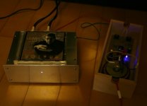
When I do power-on, the regualted rail voltage starts to increase . . . 12V, 13V, 14V . . . and after few seconds, reaches to 18V and stops there. About eight hours later, I measure the regualted rail as 18.08V. And, I measure the temperature on the surface of Q5 as 45 deg C.
The constant current through Q2 is 60mA. I can say that about 10mA is shared by zenner, diff pair and output voltage sampling circuit. And, the remaining 50mA is shared by Q5 and load (B1 buffer). As I roughly estimate total current of about 20mA through B1 (with 4* 2SK170BL), I believe the remaining 30mA is wasted by Q5.
I have used Diff pair of non-matching TRs. I have not considered the thermal coupling of them either.
I'm not using heat sinks for Q2 and Q5 partly because the current flowing through them is low and partly because this is built for a quick test. Result? I'm fully satisfied with.
By practicing this project, I feel better self-confidence, better understanding of Papa's CCS used on Zen amps and Aleph amps. Oh . . . more . . . better understanding of Papa's diy opamps . . .
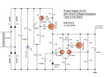
I believe this shunt regualtor has all necessary parts to be a good shunt regulator--CCS at the entrance (Q1 and Q2), reference voltage, error detector (Q3 and Q4), control element (Q5), sampling circuit and soft starter.
Am I missing any other points . . . ?
Cheers,
>><<
The constant current through Q2 is 60mA. I can say that about 10mA is shared by zenner, diff pair and output voltage sampling circuit. And, the remaining 50mA is shared by Q5 and load (B1 buffer). As I roughly estimate total current of about 20mA through B1 (with 4* 2SK170BL), I believe the remaining 30mA is wasted by Q5.
I have used Diff pair of non-matching TRs. I have not considered the thermal coupling of them either.
I'm not using heat sinks for Q2 and Q5 partly because the current flowing through them is low and partly because this is built for a quick test. Result? I'm fully satisfied with.
By practicing this project, I feel better self-confidence, better understanding of Papa's CCS used on Zen amps and Aleph amps. Oh . . . more . . . better understanding of Papa's diy opamps . . .
I believe this shunt regualtor has all necessary parts to be a good shunt regulator--CCS at the entrance (Q1 and Q2), reference voltage, error detector (Q3 and Q4), control element (Q5), sampling circuit and soft starter.
Am I missing any other points . . . ?
Cheers,
>>
<<Attachments
salas said:
Can you detect any sonic benefit as well?
My wife says no sonic benefit . . .
The combo of Bee-one and Ef-five is already too good . . .
Nevertheless, I will replace the ac adaptor with this shunt
>>
<<steenoe said:
... you might get it to work with the BC's flying your way
By the way . . .
Thanks, Steen.
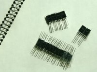
I received the TRs.
>>
<<Attachments
Babowana said:
By the way . . .
Thanks, Steen.
I received the TRs.
>>
You are welcome
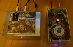
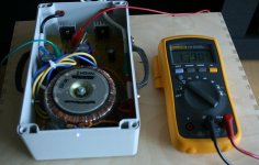
Good work on the BaboSalas shuntreg I have powered on both PSU (type A) and B1 for four days (As you see from the photo, actually, I don't have any power on-off switch. Once I plug on the power, tha's it . . . ), and measured the regulated output voltages to see how the new PSU reacts to the real operation. The output voltage has been measured at 17.80V as a constant value. Now, I fully believe that PSU works stable. I have not measured any professional interests tho . . .
What is the next . . . ? Build the type C . . . ? New TooleReg (soon) . . . ? Or, any other . . . ?
Cheers,
>><<
What is the next . . . ? Build the type C . . . ? New TooleReg (soon) . . . ? Or, any other . . . ?
Cheers,
>>
<<Attachments
I have a question about making your hand made PCB's. I have finished making some hand drawn Szekeres style headphone amp pcb's and am now working on the power supply pcb for this. I have it all drawn up, but I realized I was going to use very wide traces but I'm not sure if this will lead to soldering problems. Sorry but I've never tried to solder 2 or 3 cm wide traces before. What do you think?
Thanks
Jim
Thanks
Jim
Hi Babowana, I hope your body is as strong and healthy as your mind is these days. I've been following your B1 adventure with great interest and you've inspired me to come up with the following layout.
It's your shunt, onboard transformer and 2 channels of B1 all together. The one thing I'm uncertain of is how much cap to use on the B1 psu now that it's going to use the shunt. I only put space for smaller caps, so definitely not going to fit 15000uF caps on that board.
The third AC connector is for chassis/ground and I put a spot for an isolation resistor - any suggestions for ground modifications?
An externally hosted image should be here but it was not working when we last tested it.
Very nice, Twitchie
Papa seems to have a phobia about germs. Nevertheless, he could accept reduced size of C1 and C2 (of B1) down to 2,200-3,300uF or even smaller in this case, I believe . . .
I have no comment on the ground arragement. I normally think about an isolation thermistor instead of the resistor.
I'm just wondering where the +/gnd connection point inbetween Q5 and Q2 is about to go to.
Cheers,
>><<
Doctor says that two more chemo treatments are waiting for me . . . Now, I take a walk through a small mountain behind my apartment at least one hour everyday . . .
Papa seems to have a phobia about germs. Nevertheless, he could accept reduced size of C1 and C2 (of B1) down to 2,200-3,300uF or even smaller in this case, I believe . . .
I have no comment on the ground arragement. I normally think about an isolation thermistor instead of the resistor.
I'm just wondering where the +/gnd connection point inbetween Q5 and Q2 is about to go to.
Cheers,
>>
<<Doctor says that two more chemo treatments are waiting for me . . . Now, I take a walk through a small mountain behind my apartment at least one hour everyday . . .
- Status
- This old topic is closed. If you want to reopen this topic, contact a moderator using the "Report Post" button.
- Home
- Amplifiers
- Pass Labs
- New-building of my B1 buffer