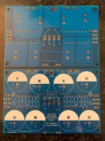
After building several Papa amps using Jeff Young’s excellent Dual Rail Decoupled Stereo Power Supply PCB, and then building a FW F2J clone and starting a new F1 clone using csample’s boards, I decided to make a “New Original” Alternate First Watt F5 Tribute Power Supply using some favorite concepts from both.
This started with Jeff’s Dual Rail Decoupled Stereo concept. Then I updated the A/C section for use in 120VAC applications, similar to the F1 PCB concept. I added one LED per side. Finally, I used 3 hole connection points for allowing quick disconnect spades, wire, or Molex/screw terminal blocks (where applicable). The quick disconnect capability should be nice for swapping boards, testing, etc.
I got my V1.0a boards in, and realized there a few optimizations to consider. So I made some updates and I'm about to send off revision V1.0b to fab.
V1.0b updates include:
Enlarged CL-60 holes. Originals fit, but they’re very tight. That KiCad footprint gets me every time.
Changed all mounting holes to pads with vias for aesthetics. Why not?
Adjusted spacing of output connectors to accept 5mm pitch screw terminal connectors. I'll want to verify this can also work with 4 quick disconnect spades side-by-side. Too tight? What is the preferred solution?
Adjusted cross board bottom output traces – routing and spacing.
Moved Line/Neutral traces towards center. Relabeled 120A/B and 0A/B.
I’m going to use one of these V1.0a versions in a Rawson Rebuild Aleph 5 project in my queue.
I’m looking for beta testers for this new PCB design. I’ll send you a V1.0a and V1.0b board. Build with one or both, up to you. Looking for about a dozen testers if interested.
To be eligible as a beta tester you must:
- Currently (or very, very soon) have an amp project and want to give this board a try.
- Post photos and talk about your build on any thread on DIYAudio.
- Offer feedback / improvement ideas for the PCBs.
- I prefer testers in North America: lower postage for me, and you will be able to use the 120VAC portion of the PCB.
Rev 1.0b boards will take appx 2 weeks to arrive. I’ll send them off this weekend to fab, and my turnaround time for PCB’s has been 9-10 days lately.
Post your name here if you want to be a beta tester. Please keep a running list by adding your name to the list.
Thanks to Jeff and Chas for the great layouts and inspiration! And thanks to Nelson for all you do for this community!!!
Attachments
-
 Dual Rail Decoupled PSU PCB 2.jpeg.jpg540 KB · Views: 1,235
 -
 Dual Rail Decoupled PSU V1.0b top.jpg98.5 KB · Views: 1,251
 -
 Dual Rail Decoupled PSU V1.0b bottom.jpg56.4 KB · Views: 1,208
 -
 New Originals Spinal Tap.JPG117.6 KB · Views: 1,253
 -
 New Original F5 Dual Rail Stereo PSU V1.0b.jpg837 KB · Views: 1,251
 -
 csample psu.jpg663.6 KB · Views: 838
 -
 Jeff Young PCB.jpg815.6 KB · Views: 630
Last edited:
I totally can build and test one or two pretty quick. I actually have two projects so can do vA and vB. Those look great, BTW!
Last edited:
Kudos on a great looking project Randy! 
Deserving of a fugly!
A couple of things to consider:
Jeff puts much more into his projects than you might initially think or he's extremely lucky and gets many things right by accident.
If you look at how he takes power for the + and - rails, he is very deliberate in runnning a single narrow track (not a pour) from the pin of the last capacitor in the CCRC. Taking it directly from the pin gives you the full benefit of a CRC but in your case, you are taking the rail (not sure if it's V+ or V-) from a copper pour which happens to connect the PI resistors and the right side V+. Imagine the scenario where you attach the output at the pin of the resistors instead of the cap along a wire which connects the 2. Electrically you might consider anywhere along the wire to be equivalent but if you attach at the resistor are you closer to just CR rather than CRC? Do not mistake me for someone who actually knows the answer because I don't have the proper training to calculate this. Others may chime in but let's just say I was on this road quite recently and just want to point out a couple of pot holes that I hit in the road
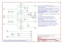
I am a satisfied user of the Jeff Young(thanks🙂) version, but I had to change the configuration. For the M2x project I needed more capacity to lower the 100Hz ripple level. The original M2 input circuit works quietly (as probably all Firstwatt amps) but some daughter cards need more ripple damping.
I measured the ripple noise and it came out about 170mV. The same was shown by spice in the simulation. Jeff checked another configuration and now I have 4x 33000uF / 4x47000uF and 0.5R resistors. The noise should be around 60 mV according to the simulation.
Somewhere on forum I read that Uniwersal PSU from the diyaudiostore works around 120mV ripple . Maybe it is worth adding some space for larger capacitors, because in this size and with only two pins there is low availability of capacitors.
Maybe someone smarter will confirm it. I'm just a regular noob🙂
Can I ask - what are the physical dimensions of this pcb? Thanks.
+1.
I’d love to test one!
Sign me up too
sign up list:
6L6
PKI - 2 (A and B)
wg45
mordikai- 2
gary s - 2 off.
dBel84
CodyT
Sign me up too
sign up list:
6L6
PKI - 2 (A and B)
wg45
mordikai- 2
gary s - 2 off.
dBel84
CodyT
I am a satisfied user of the Jeff Young(thanks🙂) version, but I had to change the configuration. For the M2x project I needed more capacity to lower the 100Hz ripple level. The original M2 input circuit works quietly (as probably all Firstwatt amps) but some daughter cards need more ripple damping.
I measured the ripple noise and it came out about 170mV. The same was shown by spice in the simulation. Jeff checked another configuration and now I have 4x 33000uF / 4x47000uF and 0.5R resistors. The noise should be around 60 mV according to the simulation.
Somewhere on forum I read that Uniwersal PSU from the diyaudiostore works around 120mV ripple . Maybe it is worth adding some space for larger capacitors, because in this size and with only two pins there is low availability of capacitors.
Maybe someone smarter will confirm it. I'm just a regular noob🙂
The biggest I’ve seen in 35dia is 47000uf/35V CDE
170x112
Okei. So just about the same as the store boards - rectifier boards.
- Home
- Amplifiers
- Pass Labs
- “New Original” Alternate First Watt F5 Tribute Power Supply PCB