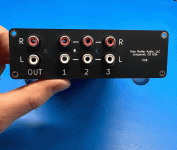
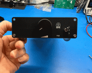
I recently had a chance to build up a new passive preamp by @audiosteve it's very nice and very straightforward. Works and sounds fantastic. 🙂
It's just a nice little box with an Alps RK27 and three-input selector switch. Front and rear panels are made from PCB material, and with the aluminum clamshell chassis extrusions, the overall package is very solid.


It's just a nice little box with an Alps RK27 and three-input selector switch. Front and rear panels are made from PCB material, and with the aluminum clamshell chassis extrusions, the overall package is very solid.
Here are some photos of the build -
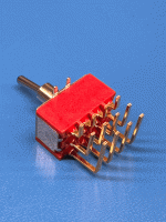
The selector switch has a LOT of pins.
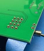
Make sure they are all in the holes, you'll probably need to adjust a few.
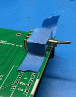
Make sure it's all flat and aligned properly, and tape to the board before soldering,
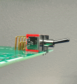
Solder the pins and the mounting tabs, and verify it's flat.
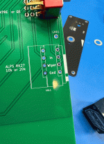
Potentiometer is next, you can see the outline for the pot, make sure it's mounted so the sets of 3 pins attach to the labeled holes. (Some, but not all, RK27 have 4 pins per row)
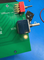
Proper alignment
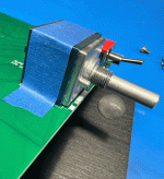
Square and level, tape down before soldering,
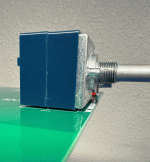
Verify it's flat when done.
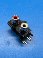
The RCA jacks are similar, they mount right to the PCB.
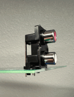
Luckily there are alignment pins on the bottom, and tiny feet on the mounting edge. easy to align, but make sure there was no movement during soldering.
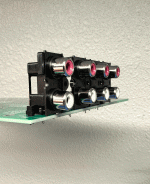
The input bank is similar, just more terminals.
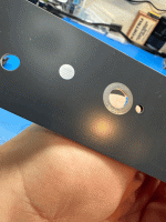
This is the INSIDE of the FRONT panel. Please note the silver dot.
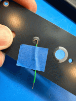
Get a small price of wire and solder to this dot.
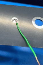
As shown here. This helps insure proper grounding of the potentiometer, eliminating noise.
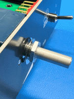
Attach the front panel to the potentiometer as shown.
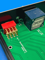
And solder the wire to the main PCB.
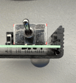
The main PCB slides into the chassis slot as shown. Properly trim any leads if needed so nothing hangs down and touches the chassis.
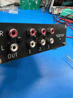
Find low-profile and preferably wide-shouldered screws to attach the RCA jacks to the rear panel. These are very important for stress relief.

The selector switch has a LOT of pins.

Make sure they are all in the holes, you'll probably need to adjust a few.

Make sure it's all flat and aligned properly, and tape to the board before soldering,

Solder the pins and the mounting tabs, and verify it's flat.

Potentiometer is next, you can see the outline for the pot, make sure it's mounted so the sets of 3 pins attach to the labeled holes. (Some, but not all, RK27 have 4 pins per row)

Proper alignment

Square and level, tape down before soldering,

Verify it's flat when done.

The RCA jacks are similar, they mount right to the PCB.

Luckily there are alignment pins on the bottom, and tiny feet on the mounting edge. easy to align, but make sure there was no movement during soldering.

The input bank is similar, just more terminals.

This is the INSIDE of the FRONT panel. Please note the silver dot.

Get a small price of wire and solder to this dot.

As shown here. This helps insure proper grounding of the potentiometer, eliminating noise.

Attach the front panel to the potentiometer as shown.

And solder the wire to the main PCB.

The main PCB slides into the chassis slot as shown. Properly trim any leads if needed so nothing hangs down and touches the chassis.

Find low-profile and preferably wide-shouldered screws to attach the RCA jacks to the rear panel. These are very important for stress relief.
Attachments
Last edited:
Last edited:
Very nice, @6L6! I saw this and Steve's B1R2 preamp at BAF last year, and he has done a nice job integrating the board, chassis and components for a very tidy look.
As always, your photos superbly show the process, and the item you are building in the best light!
As always, your photos superbly show the process, and the item you are building in the best light!
It's a pretty handy thing. I use mine all the time. If there's any other interest from others I'm sure something could be done to put together a kit.
There could absolutely be a Kit, that would be easy!
I like this @audiosteve - it's very neat!
Have you considered doing something similar as a multiple in multiple out switchbox? It seems like this kind of design philosophy could really suit something like an RCA switch for sending different sources to different DIY amps without having to get behind the rack and fiddle with cables. 😅
Have you considered doing something similar as a multiple in multiple out switchbox? It seems like this kind of design philosophy could really suit something like an RCA switch for sending different sources to different DIY amps without having to get behind the rack and fiddle with cables. 😅
@twofires Cool idea. Three in and three out would just fit that chassis. Definitely doable but I've not considered it.I like this @audiosteve - it's very neat!
Have you considered doing something similar as a multiple in multiple out switchbox? It seems like this kind of design philosophy could really suit something like an RCA switch for sending different sources to different DIY amps without having to get behind the rack and fiddle with cables. 😅
- Home
- Source & Line
- Analog Line Level
- New Passive Preamp project Gray Matter

