After building a Baby Huey amp for my dad last month, I got hooked (again) with building tube amps. Restored a Philips stereo tube amp from 1964 in the mean time and the itch got even worse 😀 I've been looking around for some designs with EL84's and there were a few that grabbed my attention, one of those being the Audio note L1 the other a design by John Broskie. The latter uses a resistive divider to set the working points of both triode halves of the first stage and the cathodyne, the AN is directly coupled but the first stages consist of a ECF80. That ECF80 seems to be a very nice tube that is cheap as a bonus.
My design goals are to design a relatively simple amp with just 3 tubes per mono side. Keeping the costs down is a priority. I have a bunch of EL84's on hand, so that seems the way to go. As the amp probably never goes to into grid current on the EL84's (small listening room, so levels are very moderate) a cathodyne for the phase splitter seems to suit well. EL84's in ultra linear are still easy to drive with a cathodyne. This leaves an unused tube half to play with for the first stage.
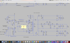
I made some designs in ltspice to test some ideas I had. The amps are loaded with a resistive load or a load that represents my speakers (electrically). Needless to say the amps respond very differently to the loads. The power supply is simulated too as is the output transformer.
I know: it is just a simulation! I still need some help to verify some component values and there are things I just don't get.
For example: the values of several decoupling capacitors in the ECF80 design are much higher than you'd expect, while the cap on the pentodes cathode is low in value. I the sims lower values lead to instability and higher distortion on low frequencies. What am I missing here??
Another example: when I use a IRF820 as a load on the second amp, the distortion is only a third of what it is when I replace it with a ZVN0545A. Why is that? The Zetex appears to be better suited for the job as Ciss and Coss are much lower.
PS. The simulation is called 'the best comparison' because these were the best designs I could make within their topologies. Not because they are simply the best you can find.
My design goals are to design a relatively simple amp with just 3 tubes per mono side. Keeping the costs down is a priority. I have a bunch of EL84's on hand, so that seems the way to go. As the amp probably never goes to into grid current on the EL84's (small listening room, so levels are very moderate) a cathodyne for the phase splitter seems to suit well. EL84's in ultra linear are still easy to drive with a cathodyne. This leaves an unused tube half to play with for the first stage.
I made some designs in ltspice to test some ideas I had. The amps are loaded with a resistive load or a load that represents my speakers (electrically). Needless to say the amps respond very differently to the loads. The power supply is simulated too as is the output transformer.
I know: it is just a simulation! I still need some help to verify some component values and there are things I just don't get.
For example: the values of several decoupling capacitors in the ECF80 design are much higher than you'd expect, while the cap on the pentodes cathode is low in value. I the sims lower values lead to instability and higher distortion on low frequencies. What am I missing here??
Another example: when I use a IRF820 as a load on the second amp, the distortion is only a third of what it is when I replace it with a ZVN0545A. Why is that? The Zetex appears to be better suited for the job as Ciss and Coss are much lower.
PS. The simulation is called 'the best comparison' because these were the best designs I could make within their topologies. Not because they are simply the best you can find.
Attachments

There is a self-inverting PP amp that you could investigate. You could use one 21AX7 to drive 2 channels with no inverter. The outputs are configured to drive one tube via the cathode signal.
There is a self-inverting PP amp that you could investigate. You could use one 21AX7 to drive 2 channels with no inverter. The outputs are configured to drive one tube via the cathode signal.
Thanks for your suggestion. I investigated the SIPP and designed something like an odd block with EL84's and a hybrid ecc83 mu-follower in the front. It was a nice exercise, but the gain of the output pair dropped to half of what it is when using a dedicated phase splitter while still keeping the same bias point. It seems to me that efficiency and output power must drop to half too. Driving EL84's with more than 12V leads to grid conduction in the output tubes. Serious limitations if you ask me. 15 or so watts is enough, but I wouldn't go lower.
On a side note: distortion in the output of a SIPP seems high. Maybe I'm just doing/simulating it wrong, so correct me in that case.
Attachments
Thanks for your suggestion. I investigated the SIPP and designed something like an odd block with EL84's and a hybrid ecc83 mu-follower in the front. It was a nice exercise, but the gain of the output pair dropped to half of what it is when using a dedicated phase splitter while still keeping the same bias point. It seems to me that efficiency and output power must drop to half too. Driving EL84's with more than 12V leads to grid conduction in the output tubes. Serious limitations if you ask me. 15 or so watts is enough, but I wouldn't go lower.
On a side note: distortion in the output of a SIPP seems high. Maybe I'm just doing/simulating it wrong, so correct me in that case.
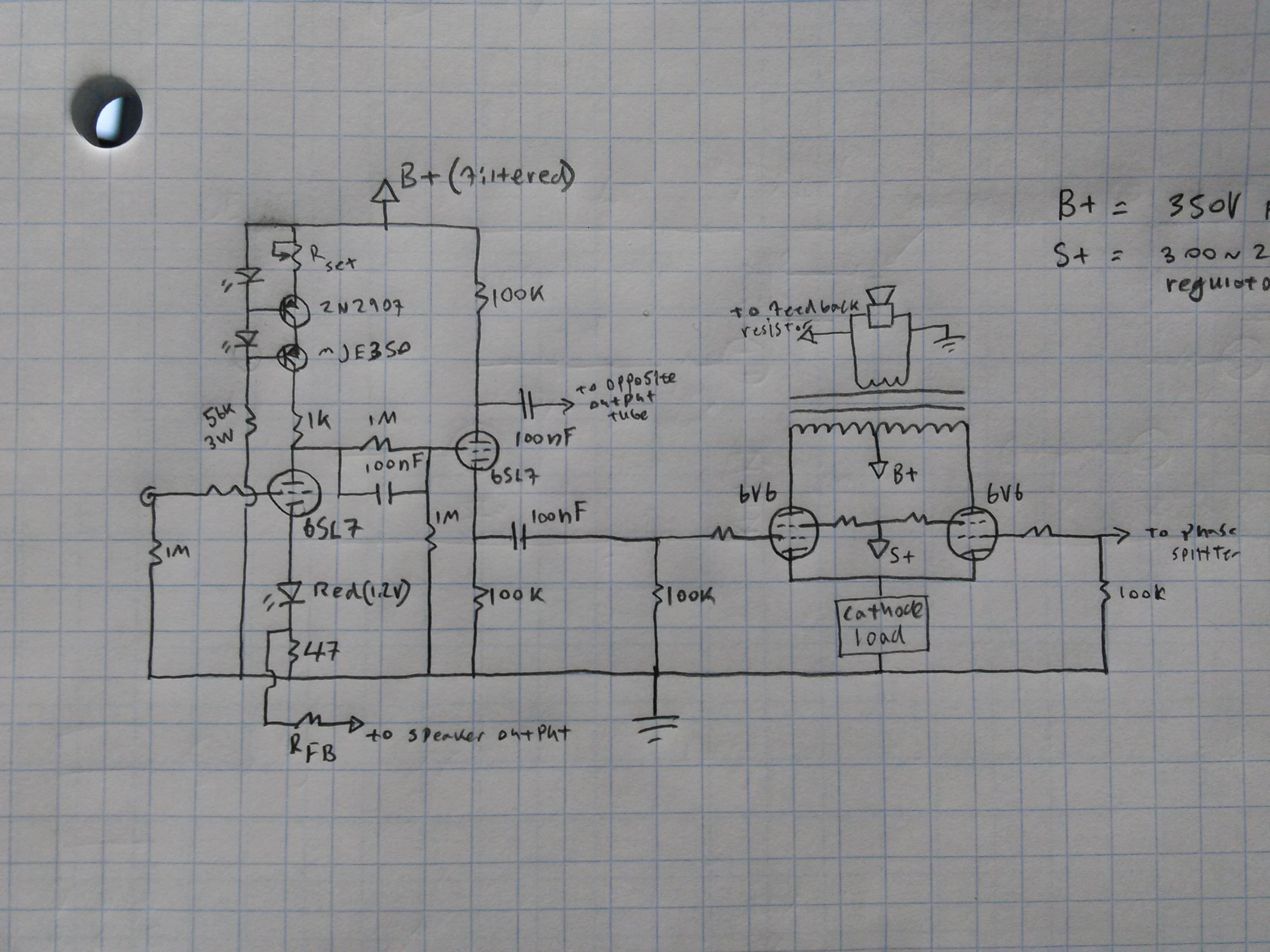
It doesn't have to be that complicated. This is the idea for a starting point I'm working on. But I'll use a 12ax7 and eliminate the EQ and volume control components and add a GNFB circuit, and build it stereo. The bias is set depending on the plate voltage and power dissipation. The drive signal stays under bias voltage. Not sure why you have a concern about grid current. Just don't overdrive it.
Attachments

Last edited:
It doesn't have to be that complicated. This is the idea for a starting point I'm working on. But I'll use a 12ax7 and eliminate the EQ and volume control components and add a GNFB circuit, and build it stereo. The bias is set depending on the plate voltage and power dissipation. The drive signal stays under bias voltage. Not sure why you have a concern about grid current. Just don't overdrive it.
It's not that I'm concerned about grid current. Point was: grid current starts to occur when the output stage delivers half the power when compared to driving the same tubes from a cathodyne or ltp. Ergo: output power must be limited too (unless I make a serious mistake).
So to recap I see the SIPP as follows: simplicity with the trade of of limited power/efficiency and higher distortion. On a side note: an ECC83 costs about the same as 4 ECF80's.
Again, I'm not against a SIPP perse, but other than simplicity, I can't see much advantages.
> grid current starts to occur when the output stage delivers half the power when compared to driving the same tubes from a cathodyne or ltp. Ergo: output power must be limited too
No. You have to apply twice the drive voltage.
If each push-pull EL84 needs 10V peak, the self-split will need 20V peak. (Still not in grid current.)
However if "distortion" is of interest, the self-split is generally not the best path.
Fisher got fine hi-fi performance with a dual-triode and a team of 7189 (hi-spec EL84). The '84 has so much gain I am not sure you really want a pentode voltage stage or fancy loading on the gain stage. As you see, high total gain makes stability problematic.
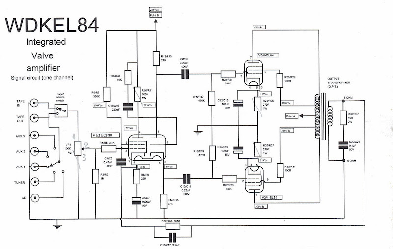
KEL 84 from World Designs.
Not new, but solid. Lots of support and upgrade stuff on their forum. Cheap as chips ECF80 (or variant) front end.
Not new, but solid. Lots of support and upgrade stuff on their forum. Cheap as chips ECF80 (or variant) front end.
I investigated the SIPP and designed something like an odd block with EL84's and a hybrid ecc83 mu-follower in the front. It was a nice exercise, but the gain of the output pair dropped to half of what it is when using a dedicated phase splitter while still keeping the same bias point.
Not a too big surprise. As in every LTP, in SIPP the cathodes are on a signal level of half the input signal, so voltage gain is halved, too.
Best regards!
Consider this as a very cheap and very nice sounding self splitter design. The driver can be replaced with a very cheap 6AU6 which will offer higher gain to boot. Two valve per channel and an overall SE signature for a fraction of the price of a decent SE OT.
http://www.diyaudio.com/forums/tubes-valves/290563-rh-slayer.html
If the tail is stiff enough a self splitter can offer comparable performance to many conventional splitter designs.
Shoog
http://www.diyaudio.com/forums/tubes-valves/290563-rh-slayer.html
If the tail is stiff enough a self splitter can offer comparable performance to many conventional splitter designs.
Shoog
Last edited:
Thanks for all your answers. For now I must leave self split topologies outside this thread. Why? Because there are already more than enough choices to make in the design topologies I posted, bringing in more designs of other topologies would make this thread cluttered and may leave initial questions I had unanswered. Apologies if I hadn't made that clear better.
One of the main goals is to aim for low distortion that is predominantly low order. The WDKEL84 offers that, as does the AN L1. There are at least a couple of designs around using a combination af a sharp cutoff pentode and a low to med mu triode to drive the EL84's, the Dynamo m3 being another one of them (yes, output tubes that need more driving voltage). All of them seem to use a healthy dose of gnf.
What I almost never see is the pentode and triode being AC coupled. To make the design a bit more flexible I designed a PCB where I can choose to couple AC or DC (the latter essentially just means leaving out some components and insert some wire bridges).
The designs I made show no sign of gremlins as Tubelab calls them in the HF range. I admit that the simulations don't take a lot of stray capacitance and leakage inductance into account.
What I do see however, is a big sensitivity spike around 1 Hz when I use 100n coupling capacitors to the output tubes or use a larger cathode bypass cap on the ecf80 pentode. Still curious why that is. Upping the grid leak resistors to 1 meg on the EL84's seems to counteract it a lot. A sim of the Leak st20 shows the same behaviour.
One of the main goals is to aim for low distortion that is predominantly low order. The WDKEL84 offers that, as does the AN L1. There are at least a couple of designs around using a combination af a sharp cutoff pentode and a low to med mu triode to drive the EL84's, the Dynamo m3 being another one of them (yes, output tubes that need more driving voltage). All of them seem to use a healthy dose of gnf.
All of your design goals are pretty much standard and there are tons of circuits to choose elements from. There aren't any really new EL84 PP designs that create significant cost benefit improvements from good vintage engineering. Most are simply minor changes that self promote themselves as a new design. Good luck with your sims. That is a hard way to get to elegant circuits if you don't know all the factors to input from the start.
All of your design goals are pretty much standard and there are tons of circuits to choose elements from. There aren't any really new EL84 PP designs that create significant cost benefit improvements from good vintage engineering. Most are simply minor changes that self promote themselves as a new design. Good luck with your sims. That is a hard way to get to elegant circuits if you don't know all the factors to input from the start.
I like thing the hard way, like getting an answer from you to a pretty simple question 😛
I like thing the hard way, like getting an answer from you to a pretty simple question 😛
OK. I went back to the start and reread everything and it seems I misinterpreted the theme of your thread. When I came to the 2 questions about the ECF80 decoupling caps and then the IFR820 and ZVN0545A, I was totally lost. Sorry 'bout that. Again, look luck with your simming.
Is this where you got the idea for the phase splitter on the bottom circuit in the sim?
Tubecad EL84/6N1P amplifier
Unexpectedly good EL84 amplifier
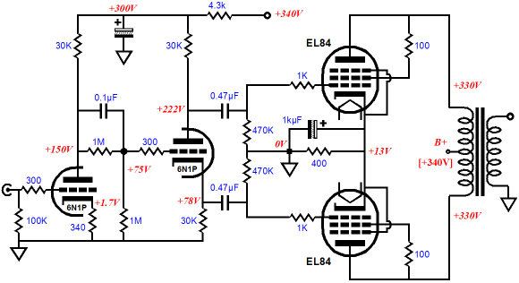
Nice little amplifier. Cheap if you build it with Russian surplus 6N1P and 6P14P, generic isolation transformer for power, and a couple of 70V line transformers even. Highly recommended! If your source is hot it also works great with 6CG7 or 6SN7 types as well with a few resistor changes to optimize it.
I believe Sy uses the same scheme for his Impasse Amplifier/unbalanced-to-balanced preamp. I use this same front end on most of my builds and experiments, as it works extremely well for a supply voltage of around ~300 volts. That step network at the split-load triode grid is nice for setting a DC bias of 1/2 the plate voltage of the amplifier triode at the splitters grid, while shorting the signal straight into the grid.
Here's my take on a nicely optimized circuit using such a scheme. Would work easily as well with EL84, and the 6N1P if you make a few changes.
Not for purists 6V6 amplifier
Tubecad EL84/6N1P amplifier
Unexpectedly good EL84 amplifier
Nice little amplifier. Cheap if you build it with Russian surplus 6N1P and 6P14P, generic isolation transformer for power, and a couple of 70V line transformers even. Highly recommended! If your source is hot it also works great with 6CG7 or 6SN7 types as well with a few resistor changes to optimize it.
I believe Sy uses the same scheme for his Impasse Amplifier/unbalanced-to-balanced preamp. I use this same front end on most of my builds and experiments, as it works extremely well for a supply voltage of around ~300 volts. That step network at the split-load triode grid is nice for setting a DC bias of 1/2 the plate voltage of the amplifier triode at the splitters grid, while shorting the signal straight into the grid.
Here's my take on a nicely optimized circuit using such a scheme. Would work easily as well with EL84, and the 6N1P if you make a few changes.
Not for purists 6V6 amplifier
I just borrowed the idea from John Broskie, who seems to have a lot of clever ideas. The amp gets some great reviews too. Our views don't differ that much: get the first triode reasonably linear, be it with a ccs or as a mu follower.
In the 6N1P-EL84 amp above what is the purpose in the sort of hybrid coupling scheme (1Meg resistors and .1u cap)? I assume that the idea was to get a somewhat lower grid voltage on the PI v.s. the plate of the VAS but how is this superior to taking the voltage divider bias from B+?
mike
mike
In the 6N1P-EL84 amp above what is the purpose in the sort of hybrid coupling scheme (1Meg resistors and .1u cap)? I assume that the idea was to get a somewhat lower grid voltage on the PI v.s. the plate of the VAS but how is this superior to taking the voltage divider bias from B+?
mike
It sets the DC bias of the phase splitter at 1/2 the voltage at the plate of the preceding stage. The capacitor couples the signal straight to the grid, otherwise you would only get half of the swing of the plate into the grid of the splitter.
Very clever and elegant arrangement, I believe Wavebourn uses it on the pyramid amp too...
Last edited:
It sets the DC bias of the phase splitter at 1/2 the voltage at the plate of the preceding stage. The capacitor couples the signal straight to the grid, otherwise you would only get half of the swing of the plate into the grid of the splitter.
Very clever and elegant arrangement, I believe Wavebourn uses it on the pyramid amp too...
How much signal can be applied on the PI grid with 75v on the grid and 78v on the cathode?
It sets the DC bias of the phase splitter at 1/2 the voltage at the plate of the preceding stage. The capacitor couples the signal straight to the grid, otherwise you would only get half of the swing of the plate into the grid of the splitter.
Very clever and elegant arrangement, I believe Wavebourn uses it on the pyramid amp too...
Yes but is there a particular reason that the voltage divider bias is taken from the VAS plate rather than B+? Also is this better than standard cathode biasing of the PI for symmetry reasons? Just want to understand as best I can the ramifications to this approach v.s. the alternatives as I think I may well give this a try on a PP 6UL8.
Nevermind, I figured it.How much signal can be applied on the PI grid with 75v on the grid and 78v on the cathode?
- Status
- Not open for further replies.
- Home
- Amplifiers
- Tubes / Valves
- New pp EL84 designs