Last edited:
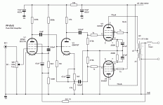
Feedback around all amplifiers causes stability issues, part of which is load angle sensitivity. Valve amplifiers with output transformers normally omit a discrete output inductor and rely on the transformer's leakage inductance, although this isn't really the same because it's inside the open/"forward" loop.
A series'd output inductor and a Zobel would be part of any really modern design. But nobody believes in modern design, only lore.
YOS,
Chris
A series'd output inductor and a Zobel would be part of any really modern design. But nobody believes in modern design, only lore.
YOS,
Chris
Feedback around all amplifiers causes stability issues, part of which is load angle sensitivity. Valve amplifiers with output transformers normally omit a discrete output inductor and rely on the transformer's leakage inductance, although this isn't really the same because it's inside the open/"forward" loop.
A series'd output inductor and a Zobel would be part of any really modern design. But nobody believes in modern design, only lore.
YOS,
Chris
Thanks, I suspected it might have something to do with the feedback loop.
Ill have to read up more on the details.
Funny the feedback doesnt include the inductor - it's right across the tranny secondary, as usual.
It's pretty much standard in solid-state amps to have an output inductor. Some avoid it, but most don't.
10 uH does sound rather high, however.
10 uH does sound rather high, however.
A filter perhaps but using thermal dissipation?
Only other thought is to remove high frequency AC (above 20KHz) from the feedback?
Inductor after a SMPS transformer before the mosfet drain (resistance) can be used with a cap to make a leak & drain for high frequency noise (ie >20KHz) - I learnt that from the LT3751 data sheet 🙂
They may be using the fact that the circuit is circular with the speaker resistor to make LCR filter? but that would push high frequency noise back down the feedback which is what I think they're doing.
Last edited:
It's pretty much standard in solid-state amps to have an output inductor. Some avoid it, but most don't.
10 uH does sound rather high, however.
I assume it it an output inductor as Chris stated pretty standard for a solid state amp. 10uH isnt all that high, for use with a 4R load.
Mondo: Yeah, it's pretty much mandatory in wide bandwidth amplifiers with loop feedback from the last active bits. The amplifier to this point has an "inductive" output impedance, and complains about any capacitive load that wants to resonate with it within its gain range.
Some hot shot solid-state designers brag about not using one, but they also promote 192Ks/s over 96Ks/s, so you judge. Valve amplifiers with transformers don't run that fast, and most folks don't care. If you made a really balls to the wall fast valve amplifier, you'd have to start worrying about load line particulars more than we normally do.
YOS,
Chris
This looks like an instrument amp (PA). Not for hifi.
Yeah perhaps a Microphone amplifier, judging by the input stage valve.
(I'm also not used to seeing 6V6 at such high bias current, but I have yet to build PP using them, only SET.)
A series'd output inductor and a Zobel would be part of any really modern design. But nobody believes in modern design, only lore.
YOS,
Chris
This gave me a bit of a chuckle. I’ve watched the sentiment slowly change here. Mosfets and other devices are showing up more and more along with the use of spice simulations. Back when I first joined the forum putting silicon in your tube amp was considered heresy. Now we’re seeing lots of interesting ideas like new ways of driving tubes.
- Home
- Amplifiers
- Tubes / Valves
- Newby question: Why is this 10uh inductor after the OPT?
