I will repeat what I wrote in other thread when first time listen to this amp: "The result was fascinating. Effortless, positioned, detailed and natural dynamic sound like someone is sitting inside a speaker. It was really astonishing compared to my previous setup".
Thanks.
I would very like to have it working with balanced input, if someone on the forum could solve this gain issue, of course if it's possible without an offboard solution.
Thanks.
I would very like to have it working with balanced input, if someone on the forum could solve this gain issue, of course if it's possible without an offboard solution.
Last edited:
I will repeat what I wrote in other thread when first time listen to this amp: "The result was fascinating. Effortless, positioned, detailed and natural dynamic sound like someone is sitting inside a speaker. It was really astonishing compared to my previous setup".
Thanks.
I would very like to have it working with balanced input, if someone on the forum could solve this gain issue, of course if it's possible without an offboard solution.
I have had a another think about this after a simulation of the circuit with the inverting input grounded - disappointingly the THD came out at 2% at 1kHz.
With a bit more time I have spotted that in the original simulation the signal to the inverting input is itself inverted.
With a balanced drive one input will already be inverted with respect to the other and so the signal feeds to the inverting and non-inverting amplifier inputs need to be in the same phase.
It is not clear whether or not you have a balanced drive from your preamplifier but as far as the simulation goes the inverting input signal symbol needs to be turned upside down.
Last edited:
With CFAs you need at least some kind of buffer for the negative input because you would be driving a 100 ohm resistor to the feedback network.
One way to get around this is to use an opamp to subtract differential inputs before going to the amp. So the amp remains SE. This way the opamp wouldn't need to be driving 100 ohms.
One way to get around this is to use an opamp to subtract differential inputs before going to the amp. So the amp remains SE. This way the opamp wouldn't need to be driving 100 ohms.
I have had a another think about this after a simulation of the circuit with the inverting input grounded - disappointingly the THD came out at 2% at 1kHz.
With a bit more time I have spotted that in the original simulation the signal to the inverting input is itself inverted.
With a balanced drive one input will already be inverted with respect to the other and so the signal feeds to the inverting and non-inverting amplifier inputs need to be in the same phase.
It is not clear whether or not you have a balanced drive from your preamplifier but as far as the simulation goes the inverting input signal symbol needs to be turned upside down.
I planned to feed the differential signal from the DAC directly without preamp.
There is no any detailed info or schematics of discrete balanced or semi-balanced amplifiers, only with opamps.
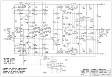
This is original balanced input schematic http://www.diyaudio.com/forums/solid-state/193923-simple-symetrical-amplifier-85.html#post2715946
With CFAs you need at least some kind of buffer for the negative input because you would be driving a 100 ohm resistor to the feedback network.
One way to get around this is to use an opamp to subtract differential inputs before going to the amp. So the amp remains SE. This way the opamp wouldn't need to be driving 100 ohms.
Like this one.
Maybe AndriyOL can take something from this one.
Attachments
Like this one.
Maybe AndriyOL can take something from this one.
Thanks for your contribution, but it's too complicated for me.
But the schematic you showed is equally complicated, and here you can see the missing buffer at the cold input (-).Thanks for your contribution, but it's too complicated for me.
He means the 4 transistor arrangement of Q31,Q32,Q35, and Q36.
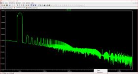
I have simulated the amplifier with a balanced signal input. Used that way it has very low distortion as can be seen from the attached FFT.
If your DAC lacks a volume control and or balanced inputs you will have to decide what approach you want to take. For instance do you want the benefits of balanced line feeds between your DAC and the amplifier or is it OK to house both the inverting circuit and buffer on new boards inside the main amplifier case.
Attachments
Thanks Mjona. It looks very promising.
How to convert this in THD+N in %? Perhaps we might need models from actual devices used to calculate the noise?
I still didn't have the dac, just plan to buy it sometime. It should have the volume control and for sure differential outputs.
Where to house inverting circuit with buffer depends on functionality and free space on the amp board. I have a limited space on heatsink. If to integrate it to the amp board it cannot be disabled if used SE input only. When I tried to ground negative input it increased a bias current of negative input transistor pair and disbalance the DC offset, don't know how will it behave with buffer.
On paper the first three places after the decimal point are zero. I am not touting here - I use simulations with a certain amount of trust to see if a design is workable or not.
If space is a problem you might think in terms of an IC based buffer on a board with adhesive plastic mounts on a vertical surface near the input terminals.
If the purchase of a DAC is not an immediate proposition then you could include the inverter on the same board as the buffer.
In that case consider making the inverter IC, socketed so it can be removed, and, providing header pin/shorting links to allow a re-route option for the ground and buffer connections for external balanced signal inputs.
Any buffer IC will need to have sufficient current to drive the low impedance of the inverting input to the power amp.
OPA551 can run off +/- 30 volts and is unity gain stable. You should be able to drop a little voltage from the lower rails in your power output stage with some series diodes and a pair of decoupling capacitors.
Otherwise you could make some +/- 15 volt rails and use pairs of LF411's if the ones used for the buffer is used in conjunction with pairs of low power transistors.
Some headphone amplifiers use the last approach so you could investigate these one and convert a choice to unity gain. Some of these projects have tidy and compact layouts - project boards for IC use are common enough to find.
Having accomplished what you have done already, you can do all of this.
Frankly speaking I don't like the ICs, I would prefer full descrete approach.
To make this schematic working will I need only buffer on negative input transistor pair? Clould you show the file you simulated? I think it could be made as add on module if space won't allow.
If you don't like ICs then you would have to dislike the entire recording process and any DAC processor.
I became involved here because keantoken provided a simulation to work with with.
I have suggested that you learn to use SPICE so you can do your own simulations and made my position of being involved here being due to keantoken having simulated your power amplifier.
I stopped using discrete components in pre-amplifier stages about 20 years ago and have not made any study of examples on this site - of which there must be a large range from which to make a selection.
Finding a circuit which can match an IC in performance in those circumstances is going to require a survey and multiple simulations which will be no small commitment of the time of others if there are any takers.
Hopefully there will be someone viewing who knows of a discrete circuit you can use and one with a SPICE simulation to back it up.
If you find such an example I will be happy to look at it.
Why do you dislike op amps and prefer discrete ?
Why re invent perfectly well designed and easy to use components ?
Descrete circuit sounds more natural than IC.
If you don't like ICs then you would have to dislike the entire recording process and any DAC processor.
I became involved here because keantoken provided a simulation to work with with.
I have suggested that you learn to use SPICE so you can do your own simulations and made my position of being involved here being due to keantoken having simulated your power amplifier.
I stopped using discrete components in pre-amplifier stages about 20 years ago and have not made any study of examples on this site - of which there must be a large range from which to make a selection.
Finding a circuit which can match an IC in performance in those circumstances is going to require a survey and multiple simulations which will be no small commitment of the time of others if there are any takers.
Hopefully there will be someone viewing who knows of a discrete circuit you can use and one with a SPICE simulation to back it up.
If you find such an example I will be happy to look at it.
I'm not happy with digital recordings, but why make things even worse?
If I'm going to use differential signal from the dac than I don't need inverting IC, only buffer on the cold input?
Your last simulation was with buffer addition? Is it too good to post it here?)
Last edited:
- Home
- Amplifiers
- Solid State
- One of the Top Solid-State CFA amp design