I've been following threads about open baffle speakers for a while now because I like the concept that promises decent spatial reproduction combined with good stereo imaging.
However, I notice in the various descriptions that there is little support from simulation when designing open baffle systems. Refinements must be determined with trial and error, often involving a lot of woodwork.
I think it is possible to do some basic simulations anyway with the Boxsim simulator. Using the ability in boxsim to simulate rectangular enclosures, this can be done as follows:
Define a box of say 100 x 40 cm but keep the depth of the box (almost) zero. Place the drivers on the baffle and let them fire to the listener. Then, to simulate the opposite sites of the drivers cones, place a second identical set of drivers on the back side of the baffle, drive them with opposite phase, and let them fire backwards. Give the drivers an almost infinite box volume and two drivers now behave like a single driver in an open baffle.
I tested this approach and it seems to work well.
The configuration I simulated consisted of a 12-inch woofer, an 8-inch midwoofer and a 1-inch waveguide tweeter.

In boxim, I entered the small/thiele parameters of the six drivers ignoring the driver self-inductances. So these were ideal drivers.
I then placed the drivers on the baffle as follows.

Then configured the three active filters to get a reasonably flat on-axis frequency response:


The whole resulted in a reasonable spatial response in the horizontal plane:


Finally, a few comments:
The above simulation should not be seen as a design description. The drivers were chosen without thorough consideration, also optimization was not very thorough.
A coaxial midwoofer should have been used for good vertical directivity.
The on-axis frequency response and phase can be exported from Boxim after which it can be imported into VintuixCAD for evaluation of impulse response and phase.
In boxim, I entered the small/thiele parameters of the six drivers ignoring the driver self-inductances. So these were ideal drivers.
I then placed the drivers on the baffle as follows.
Then configured the three active filters to get a reasonably flat on-axis frequency response:
The whole resulted in a reasonable spatial response in the horizontal plane:
Finally, a few comments:
The above simulation should not be seen as a design description. The drivers were chosen without thorough consideration, also optimization was not very thorough.
A coaxial midwoofer should have been used for good vertical directivity.
The on-axis frequency response and phase can be exported from Boxim after which it can be imported into VintuixCAD for evaluation of impulse response and phase.
Its nice to know you can do that in BoxSim but if your ultimate destination is Vituix you would do better to do the OB modeling in Vituix directly. As a first step use the diffraction tool to model your baffle and create piston directivity for each driver. You can do models for front and back separately with a Z dimension between them for baffle thickness, like you did in BoxSim. You can do even better if you generate directivity files using ABEC or AKABAK for individual drives and baffle, importing the ABEC directivity into Vituix to sum the responses and develop a crossover
VituixCAD https://kimmosaunisto.net/
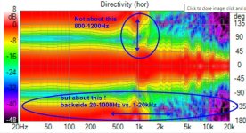
Directivity in post #2 is not particulary smooth... Baffle should be much more narrow around the midrange and tweeter. There is lots of info about dipole design in other threads here and at
www.linkwitzlab.com
http://www.dipolplus.de/
http://musicanddesign.speakerdesign.net/tech.html
To me it looks like your filters don't compensate dipole baffle loss, woofer as an example
Last edited:
Directivity in post #2 is not particulary smooth... Baffle should be much more narrow around the midrange and tweeter.
Agree with you, but I don't know how to model non-rectangular baffles in Boxsim. I admit this is a shortcoming.
Thought so, there is a first order shelf low at 150 Hz with 15 dB gain in the filter.To me it looks like your filters don't compensate dipole baffle loss
You're probably right. But as a beginner, I'm already happy to have mastered Boxsim a bit. Vintuix is still too difficult for me, and with me I think many others.Its nice to know you can do that in BoxSim but if your ultimate destination is Vituix you would do better to do the OB modeling in Vituix directly
VCAD can use ideal pistonic drivers too, without T/S data (but I don't remember how, I don't master it either)
Try this https://www.tolvan.com/index.php?page=/basta/basta.php - The Edge I use for quick sims is a simplified version of Basta
-you can use free baffle shape and multiple drivers also with T/S and filters
-but no directivity spectrograms, only overlays of off-axis responses
Try this https://www.tolvan.com/index.php?page=/basta/basta.php - The Edge I use for quick sims is a simplified version of Basta
-you can use free baffle shape and multiple drivers also with T/S and filters
-but no directivity spectrograms, only overlays of off-axis responses
Problems with simulations of multiway dipoles are many (compared to reality)
-backside radiation is not similar to frontside
-real cone/dome driver's off-axis radiation is different from pistons, actually very badly above 1kHz!
-Xmax limit and high distortion is easily met because of huge eq/boost needed for low end of passband
Practical procedure is to
1) make just simple sims of individual drivers in intended baffle to get in the ballpark of basic properties ( spl directivity and spl capacity after eq)
2) make a proto baffle, install all drivers and take real measurements of individual drivers at least horizontally 0-180deg outdoors, without eq or xo
3) analyze radiation patterns (spl graph), and distortion with quite high spl
4) apply axial spl correction for each driver - eq to flat response at least one octave beyond intended xo, analyze distortion!
5) reconcider xo freq and type, then fine-tune spl and xo
6) equalize gains of drivers
7) fine-tune delays for mid and tweeter (look at summation and step response)
3-way is too simple, low bass often needs special help.
Complexity of eq, gain and delay is best handled with multichannel dsp. Some passive components can be added like impedance flattening
Last edited:
It doesn't have to. While not perfect, basic baffle performance can be tested with Fome-Cor, cardboard, etc. With a little care I've mounted 7-inch woofers in Fome-Cor baffles. You'll need a support rib/wing, but that's a pretty common feature to employ on a dipole anyway. I normally use tape to hold it all together, since I'm often making rapid changes to the geometry, and tape speeds that up greatly.often involving a lot of woodwork
It became clear to me that the only way to achieve constant directivity and a flat on-axis spl lies in controlling diffraction effects, in particular minimizing midwoofer diffraction is essential.
Using the diffraction tool in Vituix, it is easy to determine the most optimal placement of the drivers on the baffle and the size of the baffle.
I then entered this placement into Boxsim.
Further, for convenience, I replaced the midwoofer and the tweeter by a coaxial midwoofer.
On a baffle of 70 x 40 cm the most optimal placement of the drivers turned out to be as in the drawing below:
The results surprised me.


I find the response surprisingly good. Correction with EQs proved hardly necessary. Panalty is of course that the left-right symmetry is gone. I don't know how bad this is, maybe with some town-in the adverse effects can be limited. This would just have to be tried.
Furthermore, the placement of the drivers close to the edge may cause construction problems.
Using the diffraction tool in Vituix, it is easy to determine the most optimal placement of the drivers on the baffle and the size of the baffle.
I then entered this placement into Boxsim.
Further, for convenience, I replaced the midwoofer and the tweeter by a coaxial midwoofer.
On a baffle of 70 x 40 cm the most optimal placement of the drivers turned out to be as in the drawing below:
The results surprised me.
I find the response surprisingly good. Correction with EQs proved hardly necessary. Panalty is of course that the left-right symmetry is gone. I don't know how bad this is, maybe with some town-in the adverse effects can be limited. This would just have to be tried.
Furthermore, the placement of the drivers close to the edge may cause construction problems.
From your simulation I read the following:
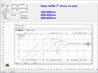
A narrow baffle gives little edge diffraction, but also little LF response. A wide baffle gives a lot of edge diffraction, but more LF response.
I suspect that the baffle I simulated, with the drivers all the way on one side, is a reasonable compromise with little edge diffraction and still a decent LF response.
Also, a baffle that is wider on one side gives room for a larger woofer.
I use The Edge for quick simulations https://www.tolvan.com/index.php?page=/edge/edge.php
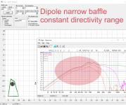
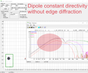
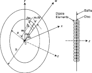
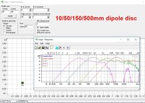
Multiway dipoles benefit from narrowing baffle - as wide as possible (or U-frame) for woofer but as narrow as possible for mid and tweeter. Think about wavelength...
driver diameter/ baffle diameter ratio is important too - dipole cancellation (when directivity is minimal) sharpness is worse with large baffle


Last edited:
I continued the simulation of the open baffle system, now however with real driver data and passive filtering.
My goal is to design a loudspeaker that can be placed in my living room and complies with the WAF. The latter means that the speaker must be as small as possible and has only to be suitable for low volumes. However, I do value open sound throughout the room and good stereo imaging in the sweet spot.
I have the following characteristics in mind:
I find choosing the right drivers difficult, especially for OB systems.
Only after you have bought and installed them do you find out that your choice was not optimal after all. I hope simulation can reduce this risk.
The first system I tried was a three-way system with a woofer, midbass and tweeter. This proved unfeasible because the cone break-up of the midbass (at about 5 kHz) is insufficiently suppressed by a first-order high-off at 3 kHz.
Second, I tried a four-way system by putting a full range between midbass and tweeter. However, I did not manage to get the crossing between full range and tweeter right.
Finally I ended up with a three-way system with woofer, midbass and full range. This does take some off-axis high but I can't hear muchabove 10 kHz anyway.
I selected the following drivers:
I then looked at the diffraction aspects with the diffraction tool in Vituix. Finally, I ended up with a simple rectangular baffle.

The baffle is 34 cm wide and in 70 cm high. In the simulation I worked with a 100 cm wide baffle in place of the woofer, this in order to get as much bass as possible. The wings, each 33 cm, become in reality the rear-facing supports.
Midbass and woofer are not low-off filtered. The SPL of the woofer is 10 dB higher than that of the other drivers. This space is used by giving the woofer an additional LF boost. The drivers cross at 250 Hz and 1 kHz.
The final filter circuit is as below:

(Remember that in the simulation, a same circuit is also needed to simulate the back side of the driver’s cones)
The simulation results:


This last graph is for diehards.
note that drivers 1, 3 and 5 are physical drivers firing towards the listener. Drivers 2, 4 and 6 are virtual drivers simulating the diffracted sound to the listener radiated from the backsides of physical driver cones.
My goal is to design a loudspeaker that can be placed in my living room and complies with the WAF. The latter means that the speaker must be as small as possible and has only to be suitable for low volumes. However, I do value open sound throughout the room and good stereo imaging in the sweet spot.
I have the following characteristics in mind:
- focus on constant directivity
- focus on correct impulse and step response
- no priority for flat SPL
- no priority for high sound level
- modest open baffle
- passive crossovers with first order filters
I find choosing the right drivers difficult, especially for OB systems.
Only after you have bought and installed them do you find out that your choice was not optimal after all. I hope simulation can reduce this risk.
The first system I tried was a three-way system with a woofer, midbass and tweeter. This proved unfeasible because the cone break-up of the midbass (at about 5 kHz) is insufficiently suppressed by a first-order high-off at 3 kHz.
Second, I tried a four-way system by putting a full range between midbass and tweeter. However, I did not manage to get the crossing between full range and tweeter right.
Finally I ended up with a three-way system with woofer, midbass and full range. This does take some off-axis high but I can't hear muchabove 10 kHz anyway.
I selected the following drivers:
- BIANCO-120B150-01 12” woofer (SB Audience)
- AL130-8 5” midbass (Visaton)
- BG80-8 3.3” full range (Visaton)
I then looked at the diffraction aspects with the diffraction tool in Vituix. Finally, I ended up with a simple rectangular baffle.
The baffle is 34 cm wide and in 70 cm high. In the simulation I worked with a 100 cm wide baffle in place of the woofer, this in order to get as much bass as possible. The wings, each 33 cm, become in reality the rear-facing supports.
Midbass and woofer are not low-off filtered. The SPL of the woofer is 10 dB higher than that of the other drivers. This space is used by giving the woofer an additional LF boost. The drivers cross at 250 Hz and 1 kHz.
The final filter circuit is as below:
(Remember that in the simulation, a same circuit is also needed to simulate the back side of the driver’s cones)
The simulation results:
This last graph is for diehards.
note that drivers 1, 3 and 5 are physical drivers firing towards the listener. Drivers 2, 4 and 6 are virtual drivers simulating the diffracted sound to the listener radiated from the backsides of physical driver cones.
- Home
- Loudspeakers
- Multi-Way
- Open Baffle simulation in Boxsim
