Look at the schematic clip below (late 1980's Philips CD player):
If one use an o'scope to probe the X_out or X_in pins of any of these two ICs, one sees a sine-wave.
Are these ICs -- using their internal oscillators -- squaring the sine-wave?
If so, why might one want to square it up before entering these ICs?
That is, certain aftermarket clocks -- like LCAudio -- feature a 74-logic buffer to square up the sinewave.
Also, certain DIYAudio projects (Andrea_mori) offer a "squarer" as an option.
None of the osc./clocks I use (for applications like the Philips schema above) output a square wave. (I'm using Flea, Kwack, or a Tent osc. with basic power-reg. ckt). EDIT: Oops...i think Kwack Clock outputs square. Built one -- still have it -- but never 'scoped it 😉
In this old DIYA thread about a Low-Noise Osc., Jocko Homo responds to the issue:
An externally hosted image should be here but it was not working when we last tested it.
If one use an o'scope to probe the X_out or X_in pins of any of these two ICs, one sees a sine-wave.
Are these ICs -- using their internal oscillators -- squaring the sine-wave?
If so, why might one want to square it up before entering these ICs?
That is, certain aftermarket clocks -- like LCAudio -- feature a 74-logic buffer to square up the sinewave.
Also, certain DIYAudio projects (Andrea_mori) offer a "squarer" as an option.
None of the osc./clocks I use (for applications like the Philips schema above) output a square wave. (I'm using Flea, Kwack, or a Tent osc. with basic power-reg. ckt). EDIT: Oops...i think Kwack Clock outputs square. Built one -- still have it -- but never 'scoped it 😉
In this old DIYA thread about a Low-Noise Osc., Jocko Homo responds to the issue:
Question: If so, is it better to feed your oscillator output into a squaring circuit first before feeding into the oscillator pin of DSP/DAC to avoid internal sqaring/timing error ?.
Jocko responds: Sine wave......And low harmonics too. That way you can put it outside of your player, feed it in at a low level without radiating crap all over the place. Then square it up once inside.
Last edited:
If you’re measuring MHz range clocks, chances are your test probes are wreaking havoc with the observed waveform. The ground lead alone has enough inductance to round off the waveform to make it look like a sine wave. There are special techniques to do this type of measurement, you might want to search the web for details.
A sine wave is a single frequency, the fundamental, whereas a square wave contains the fundamental plus the odd harmonics.
A crystal has a very high Q and acts as a very narrow filter, basically allowing one frequency, so what you get with a crystal oscillator is a sine wave.
For a digital clock circuit this sine wave is put through several logic gates that basically amplify and clip it, adding the odd harmonics to create a square wave.
The circuits inside these chips are pretty much the same as the external circuits you're looking at, an inverter or schmitt trigger with resistors to bias it into a reasonably linear region to act as the oscillator, followed by more inverters or schmitt triggers to square up the signal.
Last edited:
Hmmm ... you may have something ... I just o'scoped one of 4-pin canned oscillators in this circuit:If you’re measuring MHz range clocks, chances are your test probes are wreaking havoc with the observed waveform. The ground lead alone has enough inductance to round off the waveform to make it look like a sine wave. There are special techniques to do this type of measurement, you might want to search the web for details.
Terminating the output of the XO with a 50-ohm R (i.e, 50-ohm from output to ground), I got the crests of the "sine-wave" to flatten out a bit.
Looking at the datasheet of a CTS 4-pin osc, the Output Waveform looks trapezoidal.
Not really sure how to load my o'scope for accurate waveform metrics of oscillators???
Last edited:
To square or not to square? -- that's the question!
I can see (and have used) 74-logic around the SPDIF receiver ICs. But that's a different story (I think!).
Stated simply, give me an excuse to square up the waveform as it enters the digital IC chips (digital decoder or digital filter -- as shown in the Philips schema above)
As far as the after-market XO's (as well as the various DIY project XO's), the square-wave vs. sine-wave offerings are a bit ambiguous (as far as purpose or advantage/disadvantage).The circuits inside these chips are pretty much the same as the external circuits you're looking at, an inverter or schmitt trigger with resistors to bias it into a reasonably linear region to act as the oscillator, followed by more inverters or schmitt triggers to square up the signal.
I can see (and have used) 74-logic around the SPDIF receiver ICs. But that's a different story (I think!).
Stated simply, give me an excuse to square up the waveform as it enters the digital IC chips (digital decoder or digital filter -- as shown in the Philips schema above)
For one thing, use a special coil spring ground tip instead of the standard wire ground lead with clip. When measuring, use a ground reference point as close to the oscillator as possible. That should help with the waveform. My own experience with this is that an ugly sine wave (more like sawtooth actually) as measured with a standard probe, improved vastly with what I mentioned above. Here is an example of a 24.576MHz clock measured:

When feeding a clock into a chip give it what the datasheet says it wants. A clock input which doubles as part of an oscillator may cope with some approximation to a sine wave, as that is probably what it will see when a crystal is present on the pin. The clock used internally within the chip will be square because every logic gate it passes through will square it up anyway - that is what logic does.
This may be an appropriate moment to remind everyone that in order to improve a circuit you first have to understand it better than the original designer.
This may be an appropriate moment to remind everyone that in order to improve a circuit you first have to understand it better than the original designer.
The on chip oscillators are typically based around an internal invertor logic gate like this.
The feedback resistor attempts to bias the gate into class A operation (look up Pierce crystal oscillator) and it would not be expected to see a squarewave voltage on the crystal.
The feedback resistor attempts to bias the gate into class A operation (look up Pierce crystal oscillator) and it would not be expected to see a squarewave voltage on the crystal.
Attachments

However ...
However, the manuals of aftermarket clocks (e.g., Tent XO, LCAudio, etc. and DIY projects) instruct one to disconnect the factory crystal (and associated passives) and connect the new clock to X_in. The new aftermarket clock outputs a square wave. The question is: with the IC's X_out pin floating, how does the IC's internal inverter "see" the new clock?
I have used some XOs that output a "square" wave -- going right into X_in and, sonically, all was good (and improved over orig. crystal).
------------------
Some resources on this topic:
Quartz Crystal Oscillator and Quartz Crystals
Is the output waveform of a crystal oscillator always a sinewave?
Right!The on chip oscillators are typically based around an internal invertor logic gate like this.
The feedback resistor attempts to bias the gate into class A operation (look up Pierce crystal oscillator) and it would not be expected to see a squarewave voltage on the crystal.
However, the manuals of aftermarket clocks (e.g., Tent XO, LCAudio, etc. and DIY projects) instruct one to disconnect the factory crystal (and associated passives) and connect the new clock to X_in. The new aftermarket clock outputs a square wave. The question is: with the IC's X_out pin floating, how does the IC's internal inverter "see" the new clock?
I have used some XOs that output a "square" wave -- going right into X_in and, sonically, all was good (and improved over orig. crystal).
------------------
Some resources on this topic:
Quartz Crystal Oscillator and Quartz Crystals
Is the output waveform of a crystal oscillator always a sinewave?
Both sine or square wave is accepted by the X_in. The difference is that X_in might have some switching incertainity that could cause some jitter when fed from a relatively slowly changing waveform like a sine. With a square you eliminate this incertainity, and the switching happens exactly at the fast edge transition. So the resulting jitter is determined by that of the external clock (mostly, the internal gates still add to it).
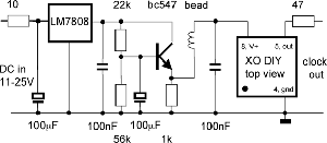
On the issue of measuring the waveform via an o'scope, Elso's Kwack-Clock instructions note the following:
I might post some o'scope shots shortly ...
With a 50 Ohm home-made probe a squarewave can be seen on the scope. My
home-made probe consists of a 50 Ohm coax cable and 50 Ohm from core to
ground at the scope end.
An ordinary probe gives kind of a distorted triangular wave shape.
If you have a scope with enough bandwith you will only see a squarewave if
you use a homemade probe of 50 Ohm coax cable terminated at the scope with
50 Ohm from core to shield. Standard probes distort the waveform. Measure
before the 0.01µF coupling cap!
I might post some o'scope shots shortly ...
X_out is an output pin, connected to the output of the internal inverter. X_in is an input pin, connected to the input of the internal inverter. The clue is in the name, and the arrows on the diagram you showed us.hollowman said:The question is: with the IC's X_out pin floating, how does the IC's internal inverter "see" the new clock?
- Status
- Not open for further replies.
- Home
- Source & Line
- Digital Line Level
- Oscillator output: sine-wave vs. square-wave?