Hello,
For now, the best results i have is with the ada4945-1, but adding some tweak because the part behavior is not well documented.
Hi Frex,
Could you tell more about your tweaks and experience with the ada4945-1?
I am close to mounting an ada4945-1 test board, which I plan to test as a driver for the AK5394A. Your findings could probably be very useful.
Hello,
I'm not very familiar with mechanical software, but even if FreeCAD seem a little bit difficult to use,
anyway after some time it do the job well and for now i can do what i want.
I must admit that i prefer to use in general open-source solution.
Another point is that there some tool allowing easy CAD interface between Kicad and Freecad.")
JenSH,
First, there is an inconsistency between the AD datasheet and the eval board.
The bottom pad of the IC is connected to ground in EVM but the datasheet
say explicitly to connect it to negative rail !
You can look my complete post on AD support on link here,
you will see all the story. I hope that will help you.
Regards
Frex
I'm not very familiar with mechanical software, but even if FreeCAD seem a little bit difficult to use,
anyway after some time it do the job well and for now i can do what i want.
I must admit that i prefer to use in general open-source solution.
Another point is that there some tool allowing easy CAD interface between Kicad and Freecad.
JenSH,
First, there is an inconsistency between the AD datasheet and the eval board.
The bottom pad of the IC is connected to ground in EVM but the datasheet
say explicitly to connect it to negative rail !
You can look my complete post on AD support on link here,
you will see all the story. I hope that will help you.
Regards
Frex
Thanks.
In my case I have connected the supply and the center pad to GND, planning to use a 5 V supply.
It will be interesting to see if using only a single sided 5 V supply will give any downsides.
Worst case I can probably still apply a -2.5 V and +7.5 V supply. I won't be able to use the clamp function though with the current layout.
So, not really a conclusion on your support question to ADI.
If it can be of any help, I can report some of what I experienced during the development of the RTX6001.
At some points in time I had instability in the input stage, leading to oscillation in the 8 to 9 MHz region, in one case around 12.5 MHz. In my case I could measure it with an oscilloscope.
It gave a result similar to what you have seen, with a large increase in the distortion level. In one occation it went from -127 dB THD to -95 dB.
My guess is that you actually have some instability, most likely caused by the long input traces. Perhaps it is only present in the input stage of the ADA4945-1, so that you don't see it on the output? The fact that it only occurs when you use the full bandwidth also points towards instability.
I don't have any practical experience with the device (yet), so don't take it for more than an attempt to help, based on experience with a similar problem although that was using a completely different circuit.
By the way, do you have any experience with performance differences between a 5 V only supply and a +7.5 and -2.5 V supply?
May I say that not by accident they have invented that FB node.. That it is brought out directly beside the input pins. These amps are not that high speed, and still, they can be more picky than a real high speed amp.
So by design it is intended that a 0603 or even smaller feedback resistance is put directly at the pins..
Instead I see that a full trip including the relay contacts is placed there.. I feel that it is stretching a bit too much.
If I would face this problem I would cut out everything, would place a single small feedback resistance as intended, and would try that way, if the instability is still there..
Also, I could not see how the ground layer is formed. Is it cut out in the input pins/traces zone? That had happened to us already once, too much dispersed capacitance on the input pins. (and that was without that extra amount of traces/ relay..)
I'm just thinking out loud, please bear it with me..
Usually this can be seen, but not with a scope. Best is a network analyzer, then a spectrum analyzer or a good scope with spectrum an. /FFT function.
Ciao, George
Hello,
II tried many things (some suggested by AD) without found any evidence
of oscillating behaviour.
I know that the signal path i use is quite large than it would be,
but the adopted topology i used require this and i have done it whith great care.
I my mind as Joseph K say the stray capacitance between feedback traces
and ground planes add some capcitance and i really thing that it disturb
the AD4945-1 input stage.
For finishing, i successfully cancelled the THD spurious by adding a small
RC network between IN+/IN- of the FDA, near it.
This work well in both operation modes of ADA4945-1.
(I tried a little in 0-5V mode and it work also very well).
Frex
Hello, I am looking for a high-quality Analog to Digital converter to take the line-level analog signal from my vintage turntable and receiver and feed it to a MiniDSP OpenDRC-DA8 as my digital crossover for my upcoming DIY speakers.
The recommended route was to purchase the AN-FP converter from MiniDsp, but alas that has been discontinued.
I would like to get a high-quality digital signal, and the converters I can find such as AMAZON seem to be cheap, low-res devices for TV audio mostly...
Is the converter discussed on this thread a better alternative? Are there other options I'm not aware of? I don't necessarily want to spend hundreds of dollars, but I also dont want to cheap-out on the signal quality to the active crossover. I honestly don't know if the TV converter in Amazon will provide a good enough digital signal quality. I can see that it will use a conversion rate up to 96Khz, whereas the board on this thread goes to 192 max, but will I be able to hear the difference?
Thanks! - Six in Minneapolis.
Hello all,
Some new today, I finally achieved today the AA10M08 digital board routing of OSVA project.
The PCB are ordered for delivery in start of august.
Between that, i leave tomorrow my bench for some family holidays!
I will post extensive info on the project when I will be back.
It's on th right way, even if the project advancement is less faster than expected ...
Looks.
Frex
(Sixto: The OSVA discussed here is a big project, not yet "ready" and it's firstly intended
for high performance measurements with high sample rate.
I think you could found other device that fit better your need.
However, you can of course follow the thread and see which way the final design
will take and what we can expect from it as audio recorder )
Some new today, I finally achieved today the AA10M08 digital board routing of OSVA project.
The PCB are ordered for delivery in start of august.
Between that, i leave tomorrow my bench for some family holidays!
I will post extensive info on the project when I will be back.
It's on th right way, even if the project advancement is less faster than expected ...
Looks.
Frex
(Sixto: The OSVA discussed here is a big project, not yet "ready" and it's firstly intended
for high performance measurements with high sample rate.
I think you could found other device that fit better your need.
However, you can of course follow the thread and see which way the final design
will take and what we can expect from it as audio recorder
)(Sixto: The OSVA discussed here is a big project, not yet "ready" and it's firstly intended
for high performance measurements with high sample rate.
I think you could found other device that fit better your need.
However, you can of course follow the thread and see which way the final design
will take and what we can expect from it as audio recorder
Thank you Frex, I will continue to monitor, if only to educate myself on the state of the art. I will keep looking for a finished product too.
Six.
Hi all,
I'm back to some Holidays in "Baie de Somme", and i can now continue where I'm stayed.
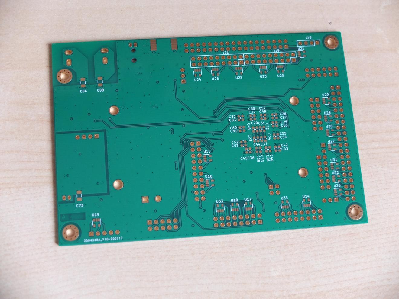
I received the new AA10M08, but unfortunately i seen immediately a mistake from me.
I forgot to change the EQFP144 footprint by one including a power-pad..
So it is missing. F**k !
Anyway, I will try to find a way to solder it and removing some copper below the 10M08
(connected to 3v3 !). This week i will also orders all parts and maybe I will found the time
to solder all of that the week after.
Some pictures below of the received board.
Regards
Frex
PS : Joseph, no worry about your interruption.
I agree with your suggestion to Sixto !
I'm back to some Holidays in "Baie de Somme", and i can now continue where I'm stayed.
I received the new AA10M08, but unfortunately i seen immediately a mistake from me.
I forgot to change the EQFP144 footprint by one including a power-pad..
So it is missing. F**k !
Anyway, I will try to find a way to solder it and removing some copper below the 10M08
(connected to 3v3 !). This week i will also orders all parts and maybe I will found the time
to solder all of that the week after.
Some pictures below of the received board.
Regards
Frex
PS : Joseph, no worry about your interruption.
I agree with your suggestion to Sixto !
An externally hosted image should be here but it was not working when we last tested it.
AA10M08 : complete parts mount.
Hello all,
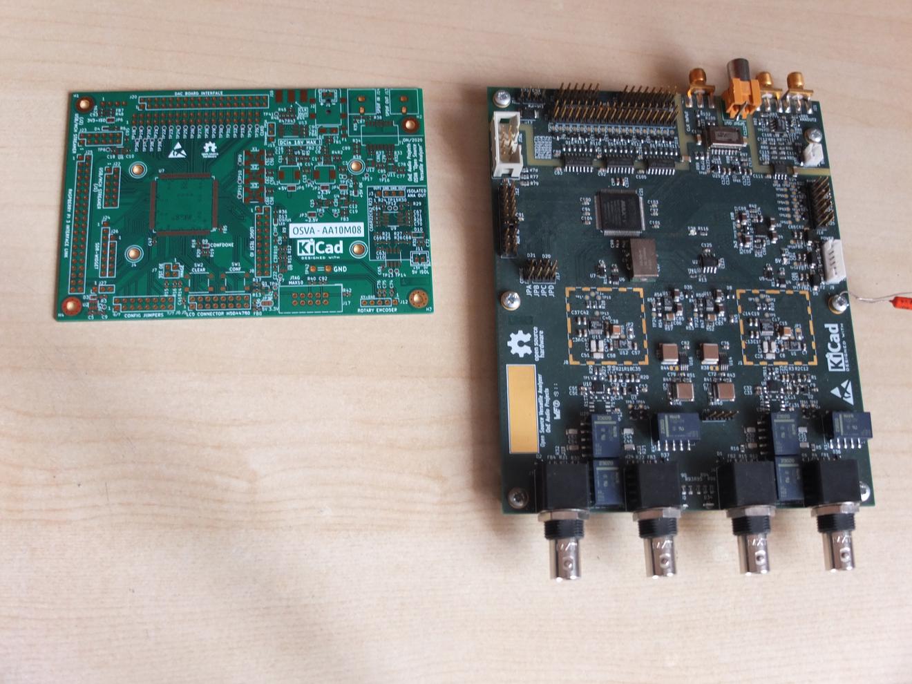
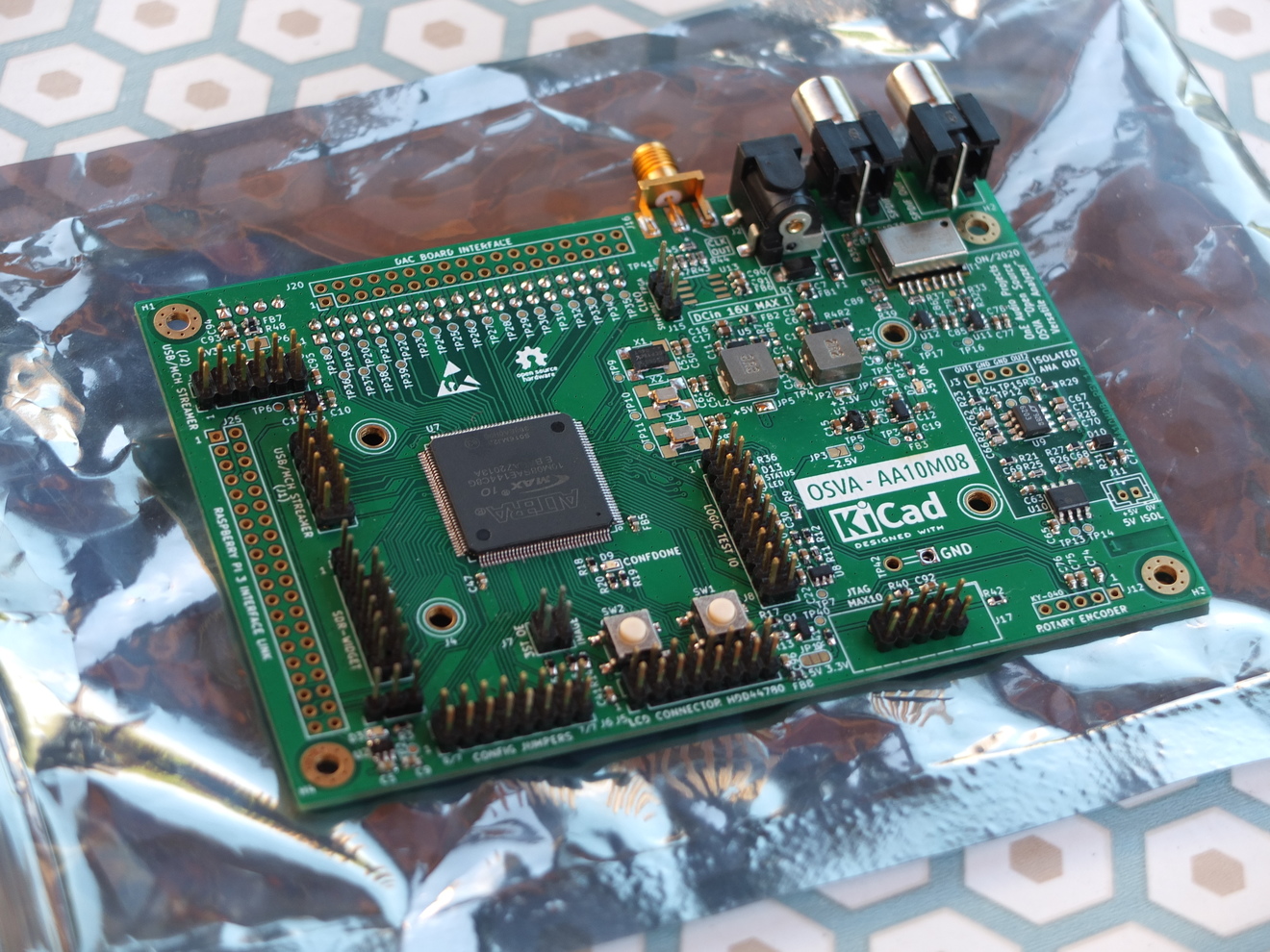
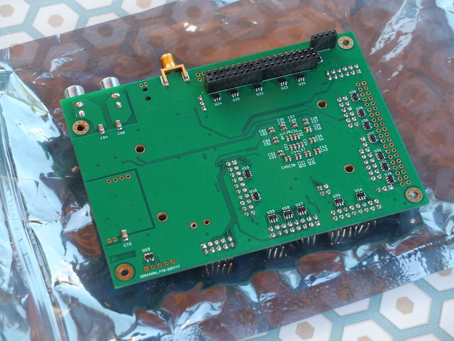
I finally solved the bottom pad connection issue of the MAX10
by adding a small copper clad.
Then and after checked that FPGA programming and all it's I/O
work fine, I soldered yesterday all parts on board
(I wrote a dedicated FPGA firmware to check all I/O separately
with only FPGA and decoupling soldered).
ou can show the results for both side below.
The first power up was good, all expected voltages are OK
(except the -2.5V output for LCD contrast, mistake choice on part ref..).
So now, It's time to work on FPGA side..
Frex
Hello all,
I finally solved the bottom pad connection issue of the MAX10
by adding a small copper clad.
Then and after checked that FPGA programming and all it's I/O
work fine, I soldered yesterday all parts on board
(I wrote a dedicated FPGA firmware to check all I/O separately
with only FPGA and decoupling soldered).
ou can show the results for both side below.
The first power up was good, all expected voltages are OK
(except the -2.5V output for LCD contrast, mistake choice on part ref..).
So now, It's time to work on FPGA side..
Frex
Hi Frex,
Nice done! Amazing project! Can't wait to see the final product.
There are some discussion before in this thread about SPI communicating.
Recently, I saw a new DAC from TI, DAC11001, 20bit R2R with good audio performance.
However, the DAC11001 is utilizing SPI protocol, not common I2S. And I am thinking if I can make a dual mono DAC based on DAC11001. But this SPI is a major issue.
I tried to search ICs that might convert I2S to SPI, or USB to SPI, but I found nothing.
This might be a bit off-topic, but do you have any idea about making audio DAC via SPI? or is your digital board are able to handle SPI signals?
Is there any solution that provides USB-SPI communication or does it must need something like DSP, MCU, FPGA/CPLD or so?
Regards,
Eric
The results presented by the TI specialist PaulFrost at DAC11001: New 20-bit, R-2R Precision DAC are not particularly convincing the DAC is suitable for audio, IMO. He even says the chips are primarily intended for very precise measurements of slower-changing signals (medical devices). Nevertheless he claims two chips with a bit of glue logic can be fed with I2S, perhaps you may want to ask him.
Hello,
Changing the data stream from I2S to SPI (audio standard) require micro-controller
or a FPGA/CPLD as underlined by Phofman.
Then, you can use many existing solution to get audio I2S data with USB
(like MiniDSP USB-Streamer or others).
I done this myself in the OSVA design, but in the other direction :
SPI of ADC to I2S and to S/PDIF also.
Regards.
Frex
Hello TNT,
I already done some DNR test (-60dB level) posted on the previous thread.
The link is here :
SAR ADC for high performance audio ADC project [LTC2380-24]
Regards.
Frex
I already done some DNR test (-60dB level) posted on the previous thread.
The link is here :
SAR ADC for high performance audio ADC project [LTC2380-24]
Regards.
Frex
There are some discussion before in this thread about SPI communicating.
Recently, I saw a new DAC from TI, DAC11001, 20bit R2R with good audio performance.
You can also consider AD5791 DAC. It's very good.
I tried to search ICs that might convert I2S to SPI, or USB to SPI, but I found nothing.
....
Regards,
Eric
There is at least one design I've seen shared by ecdesigns:
Building the ultimate NOS DAC using TDA1541A
This can be used to drive SPI DAC chips (but not AD5791 though).
Cheers!
- Home
- Design & Build
- Equipment & Tools
- OSVA - Open source Versatile Analyzer