Input Sample-and-Hold (S/H) has been part of the A/D process since the beginning of digital.
The concept of output S/H (i.e., after D/A) is obscure. I've pored over DAC datasheets (like TDA1541, 1540, etc.) and have found no mention (e.g., S/H doesn't pop up in any datasheet block diagram.)
In Ken Pohlmann's popular textbook, Principles of Digital Audio, the author discusses Output Sample-and-Hold Circuit (i.e., Aperture circuit) in the chapter on "Digital Audio Reproduction (Playback)". See below for a chapter excerpt on this topic.
The author himself admits "Many D/A converters are stringently designed to avoid switching glitches, and thus operate without an S/H circuit; aperture error is corrected in the digital filter."
In any case, has anyone encountered an Output Sample-and-Hold Circuit (i.e., Aperture circuit)?
Note that output S/H is not a "reconstruction filter", per se. However, by the very nature of S/H (i.e., via FFT analysis) , it effectively becomes a low-pass filter.
Below: a chapter excerpt from Principles of Digital Audio on this topic....
Output Sample-and-Hold Circuit
Many digital audio systems contain two sample-and-hold (S/H) circuits. One S/H circuit at the input samples the analog value and maintains it while A/D conversion occurs.
Another S/H circuit on the output samples and holds the signal output from the D/A converter, primarily to remove irregular signals called switching glitches. Because it can also compensate for a frequency response anomaly called aperture error, the output S/H circuit is sometimes called the aperture circuit.
Many D/A converters can generate erroneous signals, or glitches, which are superimposed on the analog output voltage. Digital data input to a D/A converter may require time to stabilize to the correct binary levels. In particular, in some converters, input bits might not switch states simultaneously. For example, during an input switch from 01111111 to 10000000, the MSB might switch to 1 before the other bits; this yields a momentary value of 11111111, creating an output voltage spike of one-half full scale. Even D/A converters with very fast settling times can exhibit momentary glitches. If these glitches are allowed to proceed to the digitization system's output, they are manifested as distortion.
An output S/H circuit can be used to deglitch a D/A converter's output signal. The output S/H circuit acquires voltage from the D/A converter only when that circuit has reached a stable output condition. That correct voltage is held by the S/H circuit during the intervals when the D/A converter switches between samples. This ensures a glitch free output pulse-amplitude modulation (PAM) signal. The operation of an output S/H circuit is shown in Fgr. 6.

FGR. 6 An output S/H circuit can be used to remove glitches in the signal output from some D/A converters.
From a general hardware standpoint, the output S/H circuit is designed similarly to the input S/H circuit. In some specifications, such as droop, the output S/H circuit might be less precise. Any droop results in only a dc shift at the digitization system's output, and this can be easily removed. In other respects, the output S/H circuit must be carefully designed and implemented. Because of its differing utility, the output S/H circuit requires attention to specifications such as hold time and transition speed from sample to sample.
The S/H circuit is occasionally used to correct for aperture error, an attenuation of high frequencies. Different approaches can also be used. Aperture error stems from the width of the output samples. In this case, the narrower the pulse width, the less the aperture error. Given ideal (instantaneous) A/D sampling, the output of an ideal D/A converter would be an impulse train corresponding to the original sample points; there would be no high-frequency attenuation. However, an ideal D/A converter is an impossibility. The PAM staircase waveform comprises pulses each with a width of one sample period.
(Mathematically, the function is a convolution of the original samples by a square pulse with width of one sample period.) The spectrum of a series of pulses of finite width naturally attenuates at high frequencies. This differs from the original flat response of infinitesimal pulse widths; thus, a frequency response error called aperture error results, in which high audio frequencies are attenuated. Specifically, the frequency response follows a lowpass sin(x)/x function.
When the output pulse width is equal to the sample period, the frequency response is zero at multiples of the sampling frequency, as shown in Fgr. 7A. The attenuation of the in band high-frequency response and that of high-frequency images can be observed.
At the Nyquist frequency, the function's value is 0.64, yielding an attenuation of 3.9 dB. This can be addressed with S/H circuits by approximating the impulse train output from an ideal D/A converter; the duration of the hold time is decreased in the S/H circuit. Sampling theory demonstrates that the bandwidth of the response is determined by the pulse width. The shorter the duration of the pulse, the greater the bandwidth. Specifically, if the output pulse width is narrowed with a shorter hold time, the attenuation at the half-sampling frequency can be decreased, as shown in Fgr. 7B, where the pulse width is halved. If hold time is set to one-quarter of a sample period, the amplitude at the Nyquist frequency is 0.97, yielding an attenuation of 0.2 dB. This is considered optimal because a shorter hold time degrades the S/N ratio of the system.

FGR. 7 Aperture error can be minimized by decreasing the output pulse width. A. A pulse width equal to the sample period yields an in-band high-frequency attenuation. B. In band high-frequency response improves when pulse width is one-half the sample period.
Another remedy for aperture error is frequency compensation of the data prior to D/A conversion; this can be built into the digital lowpass filter that precedes the S/H circuit. This high-frequency boost, offset by aperture error, produces a net flat response, and the S/N ratio is not degraded. A boost could also be designed into the succeeding analog lowpass filter. Alternatively, a pre emphasis high-frequency boost could be applied at the system input; the naturally occurring de-emphasis at the output S/H circuit would result in a flat response.
When an output S/H circuit is used to eliminate switching errors caused by the D/A converter during transition, the S/H circuit must avoid introducing transition errors of its own. An S/H circuit outputs a steady value while in the hold mode. When switching to the sample (or acquisition) mode, a slow transition introduces incorrect intermediate values into the staircase voltage. This problem is extraneous in the input S/H circuit because the A/D converter accomplishes its digitization during the hold mode and ignores the transition mode. However, the output S/H circuit is always connected to the system output and any transition error appears at the output. In other words, not only are the levels themselves part of the output signal, but the way in which the S/H circuit moves from sample to sample is included as well.
Distortion is greatest for high frequencies because they have a large difference between values. For example, with a 48-kHz sampling frequency, a 20-Hz signal does not change appreciably in one sampling interval; however, a high-level 20-kHz signal will traverse almost the full amplitude range. Although the distortion products themselves can be removed by the output filter, these products can internally beat with the sampling frequency to generate in-band distortion as well. To overcome this problem, the output S/H circuit must switch as quickly as possible from hold to sample mode. A square-wave response would be ideal.
In theory, this eliminates the possibility of distortion caused by transition; however, in practice, it’s impossible to achieve the necessary high slew rate, calculated to be as high as 5 V/ns (volts per nanosecond). Thus, an additional modification to the basic S/H circuit can be applied. An exponential change in amplitude from one quantization interval to the next does not create nonlinearity in the signal.
Following output filtering, this exponential acquisition results in a linear response. It can be shown that an exponential transition from sample to sample causes only a slight high-frequency de-emphasis at the output, but no distortion or nonlinearity. An S/H circuit that integrates the difference between its present and next value yields such an exponential transition. The attenuation of high frequencies in an integrate-and-hold circuit is less than that produced by the sample-and-hold process itself, and also can be equalized.
The output S/H circuit thus removes switching glitches from the D/A converter's output voltage. Hold time can be set to less than a sample period to minimize aperture error.
Many D/A converters are stringently designed to avoid switching glitches, and thus operate without an S/H circuit; aperture error is corrected in the digital filter. In some cases, the S/H function is included in the D/A converter chip. Whichever method is used, the PAM staircase analog signal is ready for output filtering, and final reconstruction.
Output Lowpass Filter
[...]
An output aperture circuit is only really needed for baseband (non-oversampling) DACs. With an oversampling DAC, the glitches are at such a high frequency that they don't have significant in-band effects.
That said, it is still useful to directly address the glitch output of a DAC chip with a passive filter network. In this case, the passive filter is really simple - you can just roll off a lot of HF since the actual audio band is well below the DAC sampling frequency. So, rather than using a convoluted sample and hold circuit, you can just lowpass the daylights out of the DAC output, and get good results.
That said, it is still useful to directly address the glitch output of a DAC chip with a passive filter network. In this case, the passive filter is really simple - you can just roll off a lot of HF since the actual audio band is well below the DAC sampling frequency. So, rather than using a convoluted sample and hold circuit, you can just lowpass the daylights out of the DAC output, and get good results.
It attenuates images, but not by much. The diagrams show this.hollowman said:Note that output S/H is not a "reconstruction filter", per se. However, by the very nature of S/H (i.e., via FFT analysis) , it effectively becomes a low-pass filter.
Some early CD players used a single time shared DAC for both L and R channels and this scenario would have been where a S/H circuit could be used to bring both channels into alignment. It doesn't seem to have been done though, at least not in the players I encountered.
That shared converter approach was used in the Sony F1 and Nakamichi DMP-100. When a signal is recorded and played back through the same machine, there will be no relative channel delays, as the half sample interchannel delay made by sharing the ADC will be undone on playback by sharing the DAC. However, for CD mastering, the half sample interchannel delay is a problem, since the CD standard does not have provision for this delay to be compensated, and summing a signal to mono with this delay can cause unwanted filtering. A few processors were offered that could undo this half sample delay digitally, allowing F1 sampled data to be used for a CD master.
While the linear sin(x)/x filtering characteristics of a S/H aperture circuit are interesting, and need to be considered, another reason why they were used was to handle nonlinear settling and slewing phenomena.
High precision, low distortion amplifiers back then tended to be somewhat slow, so the settling component of a DAC output buffer would probably have a nonlinear (slewing) component as well as linear ringing or other response abberations. So, the sample and hold allows both linear and nonlinear errors to settle out before the DAC output is transmitted further - it's not just a lowpass filter with a strange shape.
High precision, low distortion amplifiers back then tended to be somewhat slow, so the settling component of a DAC output buffer would probably have a nonlinear (slewing) component as well as linear ringing or other response abberations. So, the sample and hold allows both linear and nonlinear errors to settle out before the DAC output is transmitted further - it's not just a lowpass filter with a strange shape.
An output aperture circuit is only really needed for baseband (non-oversampling) DACs. With an oversampling DAC, the glitches are at such a high frequency that they don't have significant in-band effects.
That said, it is still useful to directly address the glitch output of a DAC chip with a passive filter network. In this case, the passive filter is really simple - you can just roll off a lot of HF since the actual audio band is well below the DAC sampling frequency. So, rather than using a convoluted sample and hold circuit, you can just lowpass the daylights out of the DAC output, and get good results.
I'm pretty sure the old Lavry Gold discrete MB DAC used exactly that, a S/H system to remove glitch energy. However I think the newest model is
different technology. Prolly DS. Times move on.
T
Some more on S/H from Chapter 4 of Pohlmann's text.
Note that is from the 6th edition (2010). Not sure why the author chose to reinforce such an obscure concept. I also have Wilkinson's The Art of Digital Audio textbook (2001), which contains no such coverage on 'output S/H'.
Note that is from the 6th edition (2010). Not sure why the author chose to reinforce such an obscure concept. I also have Wilkinson's The Art of Digital Audio textbook (2001), which contains no such coverage on 'output S/H'.
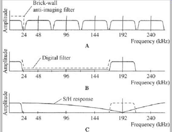
FGR. 15 Image spectra in nonoversampled and oversampled reconstructions. A. A brick-wall filter must sharply bandlimit the output spectra. B. With four-times oversampling, images appear only at the oversampling frequency. C. The output S/H circuit can be used to further suppress the oversampling spectra.
The overall effect of four-times oversampling filtering is shown in Fgr. 15. A brick-wall filter must sharply bandlimit the output spectra; with oversampling filtering, the images between 24 kHz and 168 kHz (centered at 48, 96, and 144 kHz) are suppressed, leaving the oversampling images.
The output S/H circuit can be used to further suppress the oversampling spectra, as shown. In practice, a number of considerations determine the design of oversampling filters. The sin(x)/x waveform extends to infinity in both the positive and negative directions, so theoretically all the values of that infinite waveform would be required to reconstruct the analog signal. Although an analog filter can theoretically access an infinite number of samples for each reconstruction value, a finite impulse response filter, as its name implies, cannot. Thus the oversampling filter is designed to accommodate the number of samples required to maintain an error less than the system's overall resolution. In the example above, only four coefficients were used, but as many as 300 28-bit coefficients might be needed; in practice, perhaps 100 coefficients would suffice. However, because the sin(x)/x response is symmetrical, only half the coefficients need to be stored in memory; the table can be read bidirectionally. As noted, the multipliers in a digital filter increase the output word length.
The output word cannot simply be truncated; this would increase distortion. The word should be redithered.
Last edited:
- Status
- Not open for further replies.
- Home
- Source & Line
- Digital Line Level
- Output Sample-and-Hold Circuit (i.e., Aperture circuit)