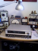
Harman Kardon SR600 (SR 600) equipped with Germanium Power Devices H43020418
by post #12 about
http://www.diyaudio.com/forums/soli...n-harman-kardon-citation-b-1963-1964-a-2.html
you will find the schematics, posted from "Orit" in Italy.
Thank you very much therefore.
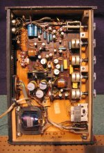
This must be one of the first solid state receivers from Harman. Phase splitter transformer is also still in use cause the at that time not available NPN germanium types
Who knows about the industry type and brand name of Harman Kardon's factory number
H43020418
by post #12 about
http://www.diyaudio.com/forums/soli...n-harman-kardon-citation-b-1963-1964-a-2.html
you will find the schematics, posted from "Orit" in Italy.
Thank you very much therefore.
This must be one of the first solid state receivers from Harman. Phase splitter transformer is also still in use cause the at that time not available NPN germanium types
Who knows about the industry type and brand name of Harman Kardon's factory number
H43020418
Attachments


Last edited:
Yes, this set looks identical to the SR-900 I repaired recently. A sticker on the back tells it was sold in Los Angeles, so I suppose it was brought to Italy individually, by the private owner.
Schematic from Lansing's "Solid State Energizer Transducer" (post #5, #6 and #46) still needed.
This would be highly appreciated for a cost estimate to perform service.
This would be highly appreciated for a cost estimate to perform service.
This solid state integrated amplifier from Cabasse I have also found by chance. It is equipped with germanium power devices. Perhaps it was the first solid state amp from this brand. Schematic and model No wanted.
Very special for that time is the dual monaural Baxandall equalizer unit so as the icon for the balance regulator. This amp haven't to do with that one from last (third) advertisement photo.
According to this guy on a french forum : Audio Vintage Le forum - Afficher le sujet - Cabasse POLARIS 20T2, the amplifier is a Polaris 20T2.
There was also a similar tube amp, the Polaris T : Polaris T - Forum Cabasse
View attachment JBL-SE401-402-1964-pwr-sch.pdfSchematic from Lansing's "Solid State Energizer Transducer" (post #5, #6 and #46) still needed.
This would be highly appreciated for a cost estimate to perform service.
Philips GH295: very clever design
I am presently trying to restore/upgrade one of these little gems. The footprint is as small as an A4 sheet of paper. Weight is only 2.5 Kg.
The attachments are thanks to Welcome to www.oudio.nl !
Just wanted to say I'm really amazed at the ingenious electronic design of this amplifier (release in 1966): for budget reasons, the power transformer has to be small, and subject to voltage drops even at moderate volume levels.
At that time, no voltage regulator chips were available, just the first, low-current zener diodes.
What they implemented is a 20-0-20 V AC secondary, which gives 27 V DC at zero volume, a zener-regulated 18 V voltage amplifier section, and a non-symmetric output stage, where the center is at 9 V, so that one PNP AD149 has 9 V Vce, the other has 18 V Vce decreasing with current increase.
In this way I think that the output stage gets balanced at maximum power, while the unbalance at low power is not very important. The effect of sagging voltage is thus minimized.
Actually the sound of this small amp is VERY nice, if not HiFi, and it's what I call "Electrovoice like", because the schematics is similar to the EV 1144.
Low feedback gives a marvellous "3D" impact to music.
Note also the very low (10 kpF) series capacitor at the input. Together with the 15 kpF feedback capacitor it keeps the frequency response uniform, without excessive loading of the input. If you try to put a bigger series capacitor, the input stage overloads.
I think the only worthwhile modifications could be a 7918 instead of the zeners + 100 Ohm resistor, removal of the tuner feed supply, and a bigger filter capacitor (3300 uF ?). A Led instead of the incandescent bulb could save some more mA. I want to keep small output capacitors because bass is already a bit on the high side now.
Attachments

Very strange output stage that isn't fully symmetrical.
The reason for this design is-I believe-both of a economical nature and technical.A zener voltage cannot be achieved without tapping from a higher voltage through a resistor,so they simply use what there is and create this lower 18V stabilized voltage and let the halves get 9V each in the bias chain.A simple way of getting a more stable output stage,but on the other hand sacrificing power.
27V should normally give more than the 3,5W in this design.

Still looking for a datasheet of the "ST610"I don't find informations, whether this model was the first solid state amplifier from Luxman. Also no data sheet and informations about Sanken's "ST-610" in TO-3 outline (see attached pics).
About the ST-615 I have found this:
ST615 datasheet and Application Note, Data Sheet, Circuit, PDF, Pinout | Datasheet Archive
Hi tiefbassuebertr
Can I interest you in a swap/trade ?
I have some NOS transistors (OC20 something (2) and some small metal cased transistors (don't remember p/n) and I'm looking for 2 pair of MPSU10 and MSPU60.
Ric
Can I interest you in a swap/trade ?
I have some NOS transistors (OC20 something (2) and some small metal cased transistors (don't remember p/n) and I'm looking for 2 pair of MPSU10 and MSPU60.
Ric
Unfortunately I haven't this. But other types for replacement: BF759/762Hi tiefbassuebertr
Can I interest you in a swap/trade ?
I have some NOS transistors (OC20 something (2) and some small metal cased transistors (don't remember p/n) and I'm looking for 2 pair of MPSU10 and MSPU60. Ric
http://www.donberg.ie/pics/b/bf_759.jpg
http://www.donberg.de/pics/b/bf_762.jpg
both types are also obsolete and no longer available from any manufacturers and there are only parts from remaining stock - independend of the supplier.
About
http://www.diyaudio.com/forums/soli...ver-stages-high-power-amplifier-overview.html
I have listed high voltage video types from currently production, but mostly for surface mounted design outline.
What is your application ??
Last edited:
My idea is to repair my old Cervin Vega...
The driver (MPSU10/60) in one channel are dead/fried.
I know about the replacements that are available but I want to keep it original if possible.
There is another member that has them but he is on vacations until next week so for now I will wait...
If you are interested in the old transistors (I don't have use for them) PM me.
Ric
Hello,If anybody has schematics for the Sanyo G-2615N it would be much appreciated.
Cheers Simon
Cheers Simon
Supplement to post #98 - Luxmann SQ503
http://www.diyaudio.com/forums/soli...lacement-luxman-sq-503-sq503.html#post2485805
and
ST615 datasheet and Application Note, Data Sheet, Circuit, PDF, Pinout | Datasheet Archive
Please note: the successor "SQ-503X" uses already a true complementary output buffer stage - have a look about the schematic
http://elektrotanya.com/luxman_sq-503_sch.pdf/download.html
have a look by post #3 aboutI don't find informations, whether this model was the first solid state amplifier from Luxman. Also no data sheet and informations about Sanken's "ST-610" in TO-3 outline (see attached pics).
About the ST-615 I have found this:
ST615 datasheet and Application Note, Data Sheet, Circuit, PDF, Pinout | Datasheet Archive
http://www.diyaudio.com/forums/soli...lacement-luxman-sq-503-sq503.html#post2485805
and
ST615 datasheet and Application Note, Data Sheet, Circuit, PDF, Pinout | Datasheet Archive
Please note: the successor "SQ-503X" uses already a true complementary output buffer stage - have a look about the schematic
http://elektrotanya.com/luxman_sq-503_sch.pdf/download.html
Attachments
Last edited:
I have the 6060F I am just getting ready to tear it down and give it a real serious once over. I hope I have a little luck on my side...Last year when I powered it up sounded great so we shall see. I have the black metal case unit, I can post pics along the way if anyone is interested.
Rob
Rob
I am still looking for informations about this amp...I read about
vintage amp amplifier, effects dating, serial numbers, CMI, Carlsbro, Cruise Audio
The model-No include the cabinet for the loudspeaker is "ER-123" (ER123)
I dont find any informations about the schematic and photos about the internal construction. Who knows more ??
ITT Stereo 4000L 4000 52540107 and "Belcanto 300" 52540121
This internal identical devices was one of the last design with germanium power devices (AD 149) in the output. After performing service (especially relacing of verious caps) sound is clear and tight.
Some URLs, schemas and pics:
ITT, Model: Stereo 4000L (Typ 52540107)
http://www.disquantique.com/english/view_product_uk.php?product=8428
http://www.radiomuseum.org/r/itt_stereo_4000_l_nussbaum_h.html
Graetz Stereo - Steuergerät (New-German: Receiver) "Belcanto 300" (Typ: 52540121)
http://saba.magnetofon.de/showtopic.php?threadid=3998
http://www.radiomuseum.org/r/graetz_belcanto_300.html
Attachments
-
Graetz Belcanto 300.pdf46.4 KB · Views: 168
-
ITT 4000 L incl. loudspeaker.pdf28 KB · Views: 180
-
 ITT 4000L belcanto300_stereo-decoder schem.jpg299.8 KB · Views: 496
 -
 ITT Stereo 4000 L tuning indicator-field strength .jpg40.6 KB · Views: 487
 -
 ITT Stereo 4000 L rear right-I .jpg30.2 KB · Views: 469
 -
 ITT Stereo 4000 L front-top .jpg32.8 KB · Views: 477
 -
ITT Stereo 4000L (AD149) schema power amp section.pdf12.6 KB · Views: 195
-
 ITT Stereo 4000L front top left.jpg90.1 KB · Views: 455
 -
 ITT Stereo 4000L front top right.jpg87.8 KB · Views: 112
 -
 ITT Stereo 4000L rear +top.jpg78.9 KB · Views: 130
Last edited:
The Electro Voice amplifiers 1144, 1179, 1244x and the receiver 1180 I discover by chance - I have never seen before. Looks very nice. Service manuals for two of this models you will find about
Service Manual free download,schematics,datasheets,eeprom bins,pcb,repair info for test equipment and electronics
No OTL topologies and germanium power devices in use.
About the 1144a you will find this one:
http://hifigoteborg.se/Electro-voice ev-1144a spec.htm
and here the 1144 pics:
I have an 1144 that I bought new in 1967. It still runs well with the exception of noisy pots and dirty switches. The indicator bulbs are burned as well.
Just downloaded the manual. I could take new fresh photos if anyone is interested.
I love this little amp. I have used it only to occasionally test speakers in the last 20 years, but did use it continuously from 1967 to 1990.
I am planning on replacing the indicator bulbs and freshening it up soon.
Last edited:
- Home
- Amplifiers
- Solid State
- Overview of Brands and Models from first Solid State Audio Amplifier Components want