I think I have all or most of my parts now except the case, sc i can at least assemble the PCB.
Problem is I'm away on holiday for a week in a few days time so I don't think it worth starting until I get back.
One thing I would like to ask is does anyone have any advice or tips on matching the transistors? I have 20 BC546's and 10 ea of BD139/140.
Not sure what I need but I have an old 465B scope which still works OK, 2 digital meters (none have transistor tests on them) and an old valve Sig-geny which I'm not sure works or not. Oh, also a 0-20v PSU with a 5v TTL output.
If anyone is interested I'm happy to show photos of the build after I get back, just let me know.
Cheers all
Roy.
Its a pity that you didnt manage before the vocation ... If you had the chance to listen before you will find out that the sound of the P3A is addictive.....
Happens to me ....when i am on holidays or road trip i find my self very excited to come back and listen to some music ..
Kind regards
Sakis
Happens to me ....when i am on holidays or road trip i find my self very excited to come back and listen to some music ..
Kind regards
Sakis
I get like that anyway. When I'm in a bar or some place where there's music I find myself compairing the sound with my system, and apart from the power levels I usualy prefer mine.
I must say though, I feel excited already about getting back and getting stuck in. Ive ordered a case off the 'bay' which is quite large with heatsinks down both sides. Should be large enough to add a second transformer if I decide to go dual mono at a later date.
Regards
Roy.
I must say though, I feel excited already about getting back and getting stuck in. Ive ordered a case off the 'bay' which is quite large with heatsinks down both sides. Should be large enough to add a second transformer if I decide to go dual mono at a later date.
Regards
Roy.


Right then
Back off my holiday now, so let the building commence.
I will try to post pictures of my progress from time to time for you to critique.
Hi Andrew, do you have a circuit for 'a little test jig' that I could use?
or I could use this one perhaps... Transistor_matching, - would this be suitable?
Hi Bilbon: Nice pictures, - neatly built
Regards to all
Roy.
I would not test them using that jig.
Base is shorted to Collector.
That results in Vce = Vbe. Very few circuits operate that way, Vce >>> Vbe
You can't measure base current.
But the corollary is that the Vbe of both DUT and REF is identical.
That is very important to revealing the difference or similarity of the collector current.
How do you set the collector current to match the current when in the final circuit?
Member
Joined 2009
Paid Member
I'm not sure you need to do any matching, but generally I read that matching the LTP devices can help minimize dc-offset and reduce distortion. However, it probably does more to reduce 2nd harmonic than most anything else and some 2nd harmonic distortion isn't likely to be an issue.
Anyhow, I don't see an issue using the simple approach to matching - Andrew has perhaps more experience than I but what I've done in the past is
1) hfe (base input impedance): use an old DMM to measure the hfe/beta of the transistors and try to select pairs that are reasonably close - implies they will have similar impedance into the base (helps with dc offset too). Out of a large sample of transistors (PNP and NPN) I found they were all very close except for one part - so if you don't have a meter handy it might not be anything to bother with.
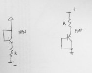
2) Vbe (nominal turn-on voltage): The idea of connecting base to collector would seem reasonable to me - i.e. good enough, for matching Vbe (Nelson uses this approach to match MOSFETs by the way and he has much more experience than I do). I would use the circuit shown attached. You size the resistor R so that you get a current flow through the device that is close to that in the final application. So if you were aiming for 1mA and had a 9V battery for your supply then you have a voltage across R of 9V less the 'diode drop' across the transistor so you want R is approx = (9-0.65)/1 kOhms, i.e. around 8k2 standard value. Then measure the voltage between the base and ground to get the Vbe of interest.
Anyhow, I don't see an issue using the simple approach to matching - Andrew has perhaps more experience than I but what I've done in the past is
1) hfe (base input impedance): use an old DMM to measure the hfe/beta of the transistors and try to select pairs that are reasonably close - implies they will have similar impedance into the base (helps with dc offset too). Out of a large sample of transistors (PNP and NPN) I found they were all very close except for one part - so if you don't have a meter handy it might not be anything to bother with.
2) Vbe (nominal turn-on voltage): The idea of connecting base to collector would seem reasonable to me - i.e. good enough, for matching Vbe (Nelson uses this approach to match MOSFETs by the way and he has much more experience than I do). I would use the circuit shown attached. You size the resistor R so that you get a current flow through the device that is close to that in the final application. So if you were aiming for 1mA and had a 9V battery for your supply then you have a voltage across R of 9V less the 'diode drop' across the transistor so you want R is approx = (9-0.65)/1 kOhms, i.e. around 8k2 standard value. Then measure the voltage between the base and ground to get the Vbe of interest.
Attachments
Last edited:
Member
Joined 2009
Paid Member
You will be close enough if you assume 1mA per transistor (2mA total). In the P3a amplifier the LTP current is set by the 'constant current source' circuit made up from Q3, D1, R7 and R8 and if you know how this CCS works you'll be able to confirm my estimate is pretty close. Using 1mA is close enough for the purpose of matching the LTP devices.
Something you learn to avoid in electronics is the direct metering of currents. The need to break the circuit to insert a meter and its effect on circuits often leads to errors, malfunction and accidents.
The total current of the LTP happens to flow through R7 (560R) ESP Fig1. Measure the quiescent voltage across this (no signal or load) and calculate current accordingly. Unless for some odd reason you need to measure current with great precision, this will be a more than adequate method, better even than setting output bias current with the 5% resistors used as a reference there - and that is standard industry practice.
The total current of the LTP happens to flow through R7 (560R) ESP Fig1. Measure the quiescent voltage across this (no signal or load) and calculate current accordingly. Unless for some odd reason you need to measure current with great precision, this will be a more than adequate method, better even than setting output bias current with the 5% resistors used as a reference there - and that is standard industry practice.
mosFETs at DC do not pass any current to the gate................The idea of connecting base to collector would seem reasonable to me - i.e. good enough, for matching Vbe (Nelson uses this approach to match MOSFETs................
There is no need to measure the Gate current. This no need for a gate resistor.
This is quite different from measuring a BJT.
mosFETs have an enormous spread of parameter values. A rough and ready Vgs using the "shorted gate to drain" method is good for batching into much closer groups.
BJTs have a tiny spread in value of Vbe. Any further measuring is not for batching, but for precison. Now the correct Vds does matter. Shorting base to collector and applying Vds = Vbe will not replicate operation in circuit when Vds>>>Vbe. The only exception is a current mirror where Vds is very low.
Member
Joined 2009
Paid Member
mosFETs have an enormous spread of parameter values...
BJTs have a tiny spread in value of Vbe....
When I measured my IRF MOSFETs the spread in Vgs parameters was very small, I was quite surprised and very pleased. I've read this is quite common these days so long as you buy them all at the same time. I have not seen such a tight grouping of parameters with my small signal BJTs. That's my rather limited experience, perhaps when you had measured your devices you found something different ?
Pictures how to?
Hi folks, I'm slowly making progress with building my boards and would like to post a picture or two on here, but I have absolutely no idea on how to do it.
If someone could offer simple instructions - or a 'help link' that would be great.
Kind regards
Roy.
Hi folks, I'm slowly making progress with building my boards and would like to post a picture or two on here, but I have absolutely no idea on how to do it.
If someone could offer simple instructions - or a 'help link' that would be great.
Kind regards
Roy.
Hi Roy,
This is pretty easy:
1) Hit "Post Reply";
2) Press "Manage Attachments" at the bottom;
3) In the small new window - "Choose File" as many times as you need (up to 10);
4) Hit "Upload". As soon as upload is done - close the small new window.
As soon as you press "Submit Reply", you message together with attached pictures will appear in the thread.
Cheers,
Valery
Thanks vzaichenko/gmphadte.
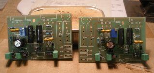
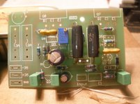
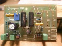
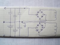
So here is where i'm up to at the moment.
C2 is installed but I had to put it underneath because of its phisical size. C1 also is too large to fit completely so I will have one end soldered to the board and the other (input end) hanging free off the board.
Looking at pic's 2 & 3, - I think Ill mount the fuse holders off the boards and use the space to mount the + and - 100uF PSU caps. Because I've split the boards into two singles I don't think there is enough space for them otherwise.
The last picture is how I intend to do the power supply. My transformer has two separate windings of 30vac each.
Hope this all looks OK so far, any comments or suggestions will be greatly appreciated.
Thanks.
Kind Regards
Roy.
Attachments
- Home
- Amplifiers
- Solid State
- P3A Comparison table ( long .... )