Parasound A21/A23 common problems and mod thread
I've been chasing an issue in one of my Parasound A21 amps for several months now and finally figured out the culprit. Its been partially dropping audio in the right channel intermittently and it mostly happens when the amp is cold, but also sometimes when hot. From my research this is a common issue with these amps (a23 uses the same input pcb), and I can't imagine how many people have abandoned their amp because of a cheap part gone bad. I wanted to post this so you guys don't have to rip out your hair figuring out an intermittent problem like this. Nothing more frustrating than spending time ans money on unsuccessfully chasing an intermittent fault.
The problem is with the input gain control pots on the back. They are the cheap Chinese garbage carbon film type. Even when they work properly, they're still a low grade part polluting the signal path, so they should be upgraded either way. The issue is how the solder pins are terminated to the resistive element. They are crimped on top of the carbon film trace and this type of connection never lasts long and usually causes problems over time, especially if you live in a humid climate. Its a shame Parasound used a cheap part like this in an otherwise great amp. It wouldn't have cost much more to use a decent conductive plastic element pot. I really like Parasound products but this sort of budget parts implementation ruins it for me.
I'm going to bypass the pot for now until I find a decent substitute that fits properly. I'm sure bourns or alps makes something that will fit. Its your basic 100k x2 audio taper pot.
EDIT - I renamed the thread title to reflect its contents more accurately
Attachments

Last edited:

Awesome thank you.
I'd suggest looking at the two ceramic wire wounds on the main board.
They feed voltage to the input board.
See pics to understand the issue here.....
Why the heck they decided to use plastic sleeving is beyond me.
Yes it took a while to repair and patch the board.
I'd also recommend replacing the four power supply caps.
In a 240vac environment they are not a long term part as they run over their rated 80vdc.
I used Cornell 27000uF 100v parts that have four pins.
You have to cut two pins off and make sure those two are insulated from the pcb.
I used a thin piece of blank fibreglass board for that.
Attachments

You must have an older model. All of my a21s have 100V caps. I can't imagine how stressed 80V caps would be running at max voltage all the time.
I see the issue with those resistors. They run HOT, somewhere around 180 degrees! I may move those away from the PCB a bit more so they don't cook the board. Thats alot of wasted power, but I guess its the cheapest way to drop all that voltage.
The XLR input jacks are also lousy. They don't hold the connector that well and there's no latch.
I ended up ordering 1.5k 10w wire wounds in a metal case, which I will mount to an aluminum plate and suspend over the pcb, so it won't potentially cook the traces.
All I could find as a direct replacemnt for the input pots is the same cheap carbon film fodder, so I ordered some linear taper conductive plastic ones that I will need to extend the lead wires a little. I ordered extras to find the best examples with tighter match between the two elements - thats one of the biggest issues with the cheap carbon pots. They are all over the place with channel balance and linearity. I chose linear taper because it allows for better adjustment in the upper range.
All I could find as a direct replacemnt for the input pots is the same cheap carbon film fodder, so I ordered some linear taper conductive plastic ones that I will need to extend the lead wires a little. I ordered extras to find the best examples with tighter match between the two elements - thats one of the biggest issues with the cheap carbon pots. They are all over the place with channel balance and linearity. I chose linear taper because it allows for better adjustment in the upper range.
The caps were running over voltage. 86v from memory.
For some strange reason they were starting to bulge (sarcasm).
With those two resistors it's more the stupid plastic leg sleeves reacting to the heat causing corrosion.
The vias and tracks on both sides of the board had been damaged.
I had to remake traces before mounting the replacement resistors higher up to get better heat separation to the board.
I can see how the pcv sleeves would gas out and corrode the connections.
I measure 90V rails on mine due to 120V AC line where I live. Can't imagine how long an 80V cap would last. The newer A21s have screw terminal caps which is better in some ways.
I bypassed the input controls until I get my parts. I run them wide open anyways but I could hear a noticeable improvement in soundstage and better low end without them in the signal path. It's already such a neutral sounding amp. I only run it balanced which sounds a bit cleaner to me than thru the RCAs. Its one of the few home audio amps that use a true balanced input stage, not the pretend pin 3 resistor to ground. Also, the current reserve is impressive. I've never pushed it into clipping and I listen very loud through my large b&ws.


An update - potentiometer and XLR replacement
First, I installed some conductive plastic clarostat pots. They sounded weird and threw off the balance throughout the whole audio range.They had a very bright, top heavy sound. Mids were less defined and bass was thinner. I was rather surprised at this.
Next, I tried some cheaper bourns carbon film replacements that are very similar to the originals, but I'm pretty sure they weren't made by the same company (looks like cheap Alps). What I then heard was a bit of a shock - they were a huge improvement, even to the originals. I suspect the factory pots had issues to begin with, mainly the right channel, which never sounded quite exactly the same to me as the left channel. I always felt the soundstage was shifted ever so slightly to the left (better sounding) side.
Listening to it, the soundstage sharpened and widened up, plus the overall sound of the amp became more precise throughout the entire audio range. It's like someone put a big audio magnifying glass in front of me. I normally don't use carbon element pots, but these Bourns replacements are really good, especially considering the cost. They run around $2 each, part number Bourns PDB182-K415K-104B. I bought 25 of them and picked out the tightest ones as a matched pair with closely matching and tracking elements.
The resulting better match in botb channels may have alot to do with why the amp sounds so much better. The old pots were not matched well. They were off by almost 10 percent between both sides and even between resistive elements. Even so, i have 2 other A21s and they both sounded better than the one I'm working on, which is also older than the others. Maybe Parasound changed potentiometer vendors.
I also changed both XLR input jacks with locking Neutrik pieces. The old XLRs were very loose fitting, all plastic Chinese cheap stuff. I had to use Teflon covered litz wire to extend the connections to the input pcb. The original screws fit perfectly in the new XLRs. I used part number Neutrik NC3FBV-1 if you ever need to replace them on your amp.
I will post other pics when I get a chance.
Attachments

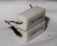
A picture of the modified XLR input jacks -
I need to add that there are two tiny pegs on the bottom of the new XLRs. They would normally locate the jack on the PCB, but these will interfere with the jack sitting centered in the panel cutout, so they need to be clipped off first.
I need to add that there are two tiny pegs on the bottom of the new XLRs. They would normally locate the jack on the PCB, but these will interfere with the jack sitting centered in the panel cutout, so they need to be clipped off first.
Attachments

Listening to it, the soundstage sharpened and widened up, plus the overall sound of the amp became more precise throughout the entire audio range. It's like someone put a big audio magnifying glass in front of me. I normally don't use carbon element pots, but these Bourns replacements are really good, especially considering the cost. They run around $2 each, part number Bourns PDB182-K415K-104B. I bought 25 of them and picked out the tightest ones as a matched pair with closely matching and tracking elements.
The resulting better match in both channels may have alot to do with why the amp sounds so much better. The old pots were not matched well. They were off by almost 10 percent between both sides and even between resistive elements. Even so, i have 2 other A21s and they both sounded better than the one I'm working on, which is also older than the others. Maybe Parasound changed potentiometer vendors.
Hi I ran to the same problem with the pots. May I know if there is a difference in term of sound quality between bypassing them and using the Bourns replacements?
I haven't noticed any discernable difference between these pots and bypassing them. Most people state that carbon film resistive elements increase even order HD, but thats more the case with tube circuits that have more voltage swing and drop across the resistors.
Thanks for this thread, as I will attempt to replace my xlr outputs as you did.I haven't noticed any discernable difference between these pots and bypassing them. Most people state that carbon film resistive elements increase even order HD, but thats more the case with tube circuits that have more voltage swing and drop across the resistors.
I have an a23, can you guide me on how to bypass the pots?
You're welcome. To bypass the pots, simply jumper the center wiper pins #2 to the full CW pins #3 on the right (viewed facing the pot shaft).
The A23 uses the same input PCB asy as the A21. The only difference is some of the resistor values are different to accommodate lower gain settings and supply voltages.
The A23 uses the same input PCB asy as the A21. The only difference is some of the resistor values are different to accommodate lower gain settings and supply voltages.
When my xlr part comes in, I'll open my amp and take a look. I might take pictures and post here first, if you don't mind, to ensure I don't do anything stupid. Below is the pot that you replaced it with. I assume it has the same pin layout as the original? Can you show me the exact pins that would bypass it? Do I need to actually desolder the pots themselves inorder to bypass? Thanks!To bypass the pots, simply jumper the center wiper pins #2 to the full CW pins #3 on the right (viewed facing the pot shaft).
Attachments

Last edited:

Thank you!Jump the center pin to the right on both pot sections. Do not remove pots or at least install 100k resistors between the left pin and center wiper locations in both sections to substitute missing pot elements. Very important!
Do you by chance know what gauge wire you used for the xlr wire? I have some 20ga solid core, and I'm wondering if it would fit into the holes.
20 gauge wire is a good choice and will easily fit. I used 18 gauge solid core silver plated copper xlr wiring with Teflon jacket.
Profiguy, how did you mount the new resistor heatsink in a secure manner?
Did you ever introduce any changes the topic discussed here:
https://www.diyaudio.com/community/threads/better-v-reg-for-parasound-a21-amp.383357/
Did you ever introduce any changes the topic discussed here:
https://www.diyaudio.com/community/threads/better-v-reg-for-parasound-a21-amp.383357/
I just finished changing out the xlr, bypassing the gain knob, and dampening my case. So after bypassing the gain, adjusting the gain knob has no effect on sound level, except when you turn it all the way down, it would almost mute the sound. Is this correct?20 gauge wire is a good choice and will easily fit. I used 18 gauge solid core silver plated copper xlr wiring with Teflon jacket.
Attachments


- Home
- Amplifiers
- Solid State
- Parasound A21/A23 volume dropout issue SOLVED