Hi everyone!
It took a while, but now I'm back 🙂
I bought a test instrument Atlas DCA55, (really nice actully!, I recommend you to buy one by yourself), and meassured all the ZTX450, 550, but them seem's ok to me. I tested IRF9610 and 610 as well. (also rechecked orientation of all transistors, all resistor was placed correctly).
After that, i really think the preamp board are ok after all!
I have reversed cables and reconnected the volume/inlet control boards and get the volume up a bit, so my focus are right now on the grounding of all signal connecting.
If anyone has an idea, you are welcome to share your experiense please!
I put 680ohm resistor where the 2K pot. are intended to be, (as instruction says), and I will test a 2K pot. too, to set up gain level.
I didnt have much time a week for this, but I will try to keep up so this will be solved.
Thank you all for trying helping me!
Best regards, Mikael
No special meter is needed to test which lead is which on bi-polars. It can be done with a simple VOM in the X100 mode.
Hi all.
New to this section of the forum.
I`m building one of these based on attached pcb. I have two, one`s now assembled but I have no output. I`m aware they are clones of the design, but simply didn`t knew when I bought them. Quality seems okay, I have traced all connections on the board and they should be fine.
All parts double checked for correct value, position and orientation in the position.
Situation: No output despite following the reference to the original Pass schematics:
Input: 0,9 volt 500 Hz from 600 ohm signal generator.
Stable 60 vdc after the 3,3 ohm resistor
All switches in open position
Q 19: Drain (D) 35 vdc, Grid (G) 0,6 vac, Source (S) 15 vdc
Q 20: D 13,5 vdc, G 4,5 vdc, S 1,5 vdc
Q 14: C 4,5 vdc, B 0,6 vac, E 0 (connected to ground so that should be correct off course)
Q 13: E 60 vdc, B 60 vdc, C 56 vdc
Q 18: 60 vdc, G 56 vdc D 34 vdc.
Trim pot adjusted to equal avalues within 10 ohm
Values are identical for both channels.
I do have a sinus shaped 5 mv ac detectable at the output, but that`s all.
My focus has been around Q 14 450 npn but I simply can`t crack the reason.
Your help and assistance will be highly appeciated.
Kind Regards
Thomas
Attachments

@ttp I have those boards as well and I think I got audio from them (it's been a while and they are packed away now so I can't check). Can't really find your parts references on the board though - where are you measuring? Also, which parts did you use for the small-signal devices and where did you get them?


Hi again.
A bit of news but unfortunately same situation.
I decided to scrap the initial pcb, remove the caps for use again, procure a new batch of transistors
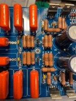
and some nice 1% Vishay/Dale reistors and build the second pcb. Resistors came in two physical sizes
despite ordered with the same power rating.
Cross checked all values, of components build the pcb and checked for the usual faults such as short circuits and incorrect
location of components.
Still no output!
I can trace the 1vac input to the Source side of the first mosfet (IRF610) and have symetrical dc voltages across the rest of the transistors at both channels but that`s about it.
I actually build a little test set-up and checked one of the mosfets (610) from the first pcb, and as you can see it works as it should.
Hope someone can assist where to look for the fault as I am at the end of my capabilities.
A bit of news but unfortunately same situation.
I decided to scrap the initial pcb, remove the caps for use again, procure a new batch of transistors
and some nice 1% Vishay/Dale reistors and build the second pcb. Resistors came in two physical sizes
despite ordered with the same power rating.
Cross checked all values, of components build the pcb and checked for the usual faults such as short circuits and incorrect
location of components.
Still no output!
I can trace the 1vac input to the Source side of the first mosfet (IRF610) and have symetrical dc voltages across the rest of the transistors at both channels but that`s about it.
I actually build a little test set-up and checked one of the mosfets (610) from the first pcb, and as you can see it works as it should.
Hope someone can assist where to look for the fault as I am at the end of my capabilities.
Attachments


- Home
- Amplifiers
- Pass Labs
- Pass Aleph P 1.7 preamp builders thread