that quote was for IRF and IRFP , so say regular mosfets
SSouths are different animals
Pa is using them in some FW products , wind up to 50W/piece , if we can believe what's written
so , keep it cool enough (palm rule) and let them bleed
SSouths are different animals
Pa is using them in some FW products , wind up to 50W/piece , if we can believe what's written
so , keep it cool enough (palm rule) and let them bleed
that quote was for IRF and IRFP , so say regular mosfets
SSouths are different animals
Pa is using them in some FW products , wind up to 50W/piece , if we can believe what's written
so , keep it cool enough (palm rule) and let them bleed
Well, pushing one to 45 is much easier than fiddling with multiple nonmatched JFETs so I hope this is true =)
Now I have one up and running but now there is that thump. I think I can do a passive solution by just reducing the onto put cap from 68mF (I know it was overkill but I had one lying around 🙂 ) to 1mF. It's a midrange amp meant to cover 300 hz and upwards so the increased cap impedance isn't an issue.
My ccs is is an inductor so that would work because:
The thump is subsonic at 1 hz or below and down there the inductor impedance will be low and thus output impedance will be low. The output caps impedance will be high and thus the thump will discharge slowly and not be a problem anymore.
Or am I deluding myself and I need something more complicated than a smaller cap?
Last edited:

easy to try , isn't it
small cap will not pass low thump
True, and it seems to have worked =)
What once was a ~ 1cm movement on the speaker is now a tiny ~ 1mm so I don't think I have to worry anymore. I found I had a few bad solderings on the source resistors so that was why the resistance was too low, so now the bias is up to 2.35A, which is close enough to my goal of 2.5A so I'll settle.
Though this was a test, for the final I'll build 4 of them with 2 in each box so I'll probably redo it as the cabling is... not that beautiful at the moment =) And then I might as well stick a pot on it too so I can dial it to 2.5A =)
Last edited:
Hmm, after some troubleshooting I've realized that the R085 really doesn't like high source impedances.
My Balanced to Single ended transformer (JT-11P-1) has 2.4k output impedance and I've used it until now in my F2J and L'amp without issues. The F2J has probably had some increased distortion high up because of it but it didn't make it sound bad at all, relaxed and nice all the way.
The DeLite with the R085 however, sounds awful when driven with a high source impedance and distorts a lot at 10khz +. There was about 15 dB more 2nd and 3rd and some higher order distortions starting to show up. The problem went away when I removed the transformer, so much more relaxing to listen to now =)
I guess I'll have to build a buffer if I want to use the transformer. The plan is to exchange the source with a single ended capable source so then I won't need a buffer which is nice =)
Last edited:
One thing I've wondered about:
If I've understood correctly the output impedance of this circuit is the drain resistance of the R085 in parallel with the current source impedance. And so what I wonder is what is the drain resistance of an R085 at normal conditions of say 20V @ 2A.
In the end what I'm wondering is if I have a current source with high enough impedance will I get a pure current source amps of several hundred ohms in output impedance or will the R085 itself limit it to some number =)
According to this post the output impedance is : Z=(V1-V2)/((V2/R2)-(V1/R1)) where 1 and 2 are voltage readings over different resistors.
I fed a 400 hz signal and got those readings:
V1 = 4.28V
R1 = 9.2Ω
V2 = 1.87V
R2 = 4.0Ω
So If I've understood correctly my output impedance is ( 4.28 / 1.87 ) / ( ( 4.28/9.2 ) - ( 1.87/4.0 ) ) = ~1000Ω.
If my calculation is correct that is. I expected it to be lower as the inductor impedance is only about ~377Ω then but if it it is that high then I'm not complaining =)
EDIT: Now it has 2.2Ω source degeneration, so that might be what is pushing up the output impedance. I want more gain though so I plan to mount bias supplies and then try with 0.33Ω and 0.66Ω and see how it performs. I assume that the output impedance should still be above 100-200 which should be enough.
Last edited:
Now I've hooked up an inducted R100 again and compared somewhat. I'll have to echo Tea-Bags findings when he compared a R100 to an R085. The R085 sounds good, but isn't as easy on the ears as the R100. There is this brightness in the background that the R085 has that the R100 doesn't. Reminds me of when I compared my then inducted R100 to an NCore, which also had that brightness.
It probably has something to do with distortion, don't know what though. I've obviously used the R100 previously with too high source impedance causing lots of HF distortion but it still sounded relaxed and nice, where the R085 didn't sound nice at all. So there seems at least to me that there is some difference in the distortion characteristic between the R100 and R085.
It probably has something to do with distortion, don't know what though. I've obviously used the R100 previously with too high source impedance causing lots of HF distortion but it still sounded relaxed and nice, where the R085 didn't sound nice at all. So there seems at least to me that there is some difference in the distortion characteristic between the R100 and R085.
if driven accordingly , there will hardly be any important difference between R085 and R100 iterations
if driven accordingly , there will hardly be any important difference between R085 and R100 iterations
There shouldn't be a difference no which is why I'm so confused. If anything the R085 has less distortion so it should sound better.
I remember Nelson talking about oscillation a bit back and how it can be prevented by using gate stopper resistors. I did put 100 ohm gate stopper but I could hook up the scope and check how waveform looks like with 10 khz square and compare to the R100.
Last edited:
I'm new to building amps and electronics in general, but I am interested in giving this project a try. I've got some electrical knowledge and am fine with a soldering gun. Anyway, throughout this whole thread, I've yet to see a schematic of what the official stereo version de-lite looks like. I've attached a drawing to see if I got the idea right. Proper star grounding scheme not included....
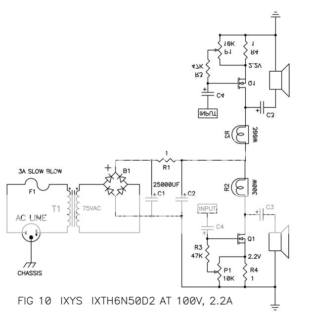
I've see numerous photos of people using two B1's and two R1's, often with several more caps (C1 and C2)....is this necessary to make the most basic stereo version of this amp? I don't believe NP's own unit shown in picture on the first page of the pdf has that....correct? I know I am using figure 10 in the schematic, but I would be building the most basic initial version...assuming the idea is right....
Last, I read about many attempts at this project having hum at first, but if I understand enough, is that because everyone is using parts bin stuff and different chassis layouts? Meaning if I build the amp EXACTLY as it looks in NP's photo, with the EXACT same parts (same specs anyway), I would not have hum?
Last edited:
You can see a nice variant of this little amp:
Amplificador Clase A pura 1 etapa Single Ended Light
regards
Amplificador Clase A pura 1 etapa Single Ended Light
regards
I was thinking of doing a choke load like this but in my case the choke has a dcr of 4.5ohms. I also would like to play with the Ixth20n50d or the SJEP120R100. I know i will have to play with the biasing etc. But is there any way to calculate the output impedienc?
By the way if I use the Ixth20n50d I may drop about 32v across it and up the bias to 2.5A I have a large heatsink and that is a 400W device so it can be pushed a little harder.
By the way if I use the Ixth20n50d I may drop about 32v across it and up the bias to 2.5A I have a large heatsink and that is a 400W device so it can be pushed a little harder.
Attachments

I was thinking of doing a choke load like this but in my case the choke has a dcr of 4.5ohms. I also would like to play with the Ixth20n50d or the SJEP120R100. I know i will have to play with the biasing etc. But is there any way to calculate the output impedienc?
By the way if I use the Ixth20n50d I may drop about 32v across it and up the bias to 2.5A I have a large heatsink and that is a 400W device so it can be pushed a little harder.
The R100 is an enhancement device so in that case you need a positive supply and not a negative one.
Output impedance on either should be high, a true current source. Say around 500-1000 or more. Which is awesome if it is a current source you want =)
I have a similar circuit for my inductor loaded R100s. The Arch-nemesis power supply works well, and it can be changed from positive to negative depending on what your mosfet/jfet needs.
The depletion mode devices seem to have a lower Drain impedance, but both
it and the enhancement type are more on the order of 100 ohms or less. In
any case, it will pretty much act as a current source.
😎
it and the enhancement type are more on the order of 100 ohms or less. In
any case, it will pretty much act as a current source.
😎
Thanks Nelson that's what I needed to know. I may be using a
crossover after this amp so now I know I will need to be looking
at a current source crossover rather than the traditional voltage
source crossover like you discussed in your Current Source Crossover
Filters article.
crossover after this amp so now I know I will need to be looking
at a current source crossover rather than the traditional voltage
source crossover like you discussed in your Current Source Crossover
Filters article.
I could catch a couple of 1000W/240V E40 light bulbs and a SANREX FBA50BA45. With a prototype the bulb had a nice glowing orange filament and the first (audio)results where not bad.Next the build, pictures and fine tuning in a few weeks.
I could catch a couple of 1000W/240V E40 light bulbs and a SANREX FBA50BA45. With a prototype the bulb had a nice glowing orange filament and the first (audio)results where not bad.Next the build, pictures and fine tuning in a few weeks.
1000 W
 that interesting 😀
how much is bulb internal resistance ?
Greetings
- Home
- Amplifiers
- Pass Labs
- Pass "DeLite" Amp from BAF