Here's a preview of the 'interview' portion of the Pearl 3 article. Enjoy!
...
This is a new phono stage from the mind of Wayne Colburn, the gentleman responsible for all of the line-level creations from Pass labs over the past 25 years. In the PassDIY tradition, this continues Wayne’s DIY phono stage series with the name Pearl 3. We had a chance to discuss with Wayne and record some of his design ideas and goals for this project.
What’s new about this Pearl?
Compared to Pearls 1 and 2, there is more gain in Pearl 3, it has greater drive on the outputs, and has a very low output impedance as a result of the complimentary follower stage.
Pearl 1 and 2 had no feedback around the front-end, whereas this does. Wrapping the input stage within the feedback loop of the opamp (creating a composite amplifier) has a number of advantages. An immediate example being that it’s very simple to adjust gain, unlike the previous Pearls.
There are many other advantages, including:
No extremely static-sensitive mosfet that often died in construction even with careful handling.
Selectable cartridge loading, both capacitive and resistive, through DIP switches on the PCB.
More possibilities for user modification, such as; power supply modifications, opamp rolling, etc…
Extremely accurate RIAA response.
Optional Balanced Line Driver for XLR out.
What do you think makes a good DIY project?
Getting it working easily is quite important - obviously it’s frustrating for builders if they have problems, but also frustrating for me, as I’m not there to help, so designing a circuit where, as long as all of the parts get nicely soldered into the proper holes, it should work with few or no adjustments. It should also be an easily repeatable circuit, with easy to source parts, and nothing super exotic. To that end, the difficult-to-source K170/K370 JFETs don’t need to be used and instead you can use in-production Toshiba 2SK209, or a number of different transistors. However, if you have a set of 2SK170, this is the perfect place for them.
Let’s talk about the input stage. It looks familiar…
Well the original basis of the front-end (FE) used in Pearl 3 dates back to the Pass Labs Aleph Ono… and similar versions of it have been used in Pearl, Pearl 2, XONO, and XP-15. Having four parallel devices right on the input from the phono cartridge greatly helps with noise, linearity, increases transconductance, and helps improve open-loop gain with lower distortion. The cascode (Q5) is beneficial for noise as the JFET drains have an optimum bias point for minimal noise ,- usually well less than 15v - which the cascode helps to set properly. Additionally, the cap multiplier circuit (Q8, C7 and attached resistors) will provide additional, and importantly, focused power supply filtering to the input stage, which because of the very small signals generated from a cartridge, noise performance is paramount. Because of all of these features, the front-end benefits the most.
The input stage is feeding an opamp. What is the idea behind that?
There are many great opamps available these days with low noise and high drive. However, when dealing with the amount of gain required for moving coil cartridges, the front-end is still going to benefit from the careful application of discrete, very low noise JFETs. So with Pearl 3, I took the quiet and optimized discrete input stage and combined it with a high-performance opamp, wrapping a single feedback loop around both. The result is a composite amplifier. Now that it has feedback, the total open-loop gain (OLG) is higher and has a lot more adjustability. The use of opamps provides great flexibility for the builder, and you can roll opamps, which many people find to be a lot of fun. Interestingly, all the opamps I’ve tried in the circuit measure quite well, but the harmonic structure seems to change between opamps, so they might actually sound different. This may have more to do with the 2nd stage, but I could see it on my Audio Precision system and HP spectrum analyzer. There are a lot of design issues that are easy to address with opamps but difficult with discrete parts - temperature tracking immediately comes to mind - and that helps with all aspects of the circuit’s performance. Also, having the feedback loop makes it easy to adjust the gain. Feedback changes the overall sound, at least to some extent. Changing overall gain results in less noise, so if you really want to tweak and tune, set R9 for the minimum value you need in your particular system.
Unlike the previous Pearls, this appears to have split RIAA equalization.
Pearls 1 and 2 were ‘all in the middle’ RIAA. It’s a little easier to make the EQ really flat if RIAA is split into two sections, and the measurements bear this out. Doing the HF first is useful as it’s comprised of attenuation, (whereas the LF pole is boost,) so an enormous amount of the circuit noise and generator noise gets attenuated. (this pole is the 0.1uF and 750 Ohm in-between U1 and U2). The 2nd stage has a very standard implementation ,- again, using easy-to-find 0.1uF and 100pF capacitors with 31.6k+220 resistors, which makes the perfect value and which are obtainable in E96 spacing. The output stage has a large-device BJT follower stage biased with LED; in addition, a J112 JFET pulls a little extra bias from the opamp and helps it towards class-A operation at normal operating points.
What is the 1M and 4.7pF in U1 doing?
Controlling the HF cutoff of the first stage up around 200K to make sure the circuit is stable and doesn’t attempt to do anything unnecessary in RF
What are the power supply requirements?
The circuit uses approximately 60mA per channel and the design voltage is +/-15vdc. Having a well-filtered raw DC supply is easy enough with a few stages of RC filtering, and the regulators are close to the load being mounted to the RIAA pcb. So PSU isn’t all that critical, but it’s an easy place to experiment and use what you want. It runs fine on +/-12vdc as well, so if you have some super secret prototype ninja PSU that only goes to +/-12v, go ahead and use it.
Anything you think is particularly cool?
There’s really nothing fancy or magical in this circuit, but with logical implementation it all works out very, very well. I think you will like it.
——————
…FAQ and other neat-o thoughts…
Things that are critical?
The RIAA components… R13, C3, R14, R15, R17, C4, C5, R18.
Things builders can change ?
Rolling opamps! You’re welcome to try any normal dual with a normal pinout. Lots have been tried, and they all have worked. You can even use a discrete part like a Sparkos or Burson.. Post your findings in the thread.
The power supply is open to many different configurations… The ‘standard’, project-supplied PSU board is a very compact and effective CRCRC implementation with on-board transformer and snubbers. Other solutions will be experimented with and posted in the thread. Mark Johnson has made an incredible PSU pre-filter that will make the input noise so quiet that all the on-board regulators will have to do is deal with load variance. Look up “UDP3” (Umbilical Driver Pearl 3) on diyAudio.com.
Have a shunt reg or SuperReg? Go ahead! Something new and amazing? Go ahead. Just needs to be bipolar and around +/- 15V. Want to build it completely dual mono? That would be so cool!
Might you get away with slightly lower value coupling caps?
Maybe, but why bother?
But I really want to change the capacitors, it’s what audiophiles do…
The cap multiplier capacitor (C7) can be bigger if you like.
If you have a bipolar cap for C8, you may use it there. Also worth mentioning that C8 has very little voltage across it, so even a 16V cap will be more than enough.
PSU caps near the regulators can be bigger, use whatever you have that can fit., One sometimes overlooked advantage of the 7800/7900 series regulators is how much capacitance you can hang downstream of them with the regulators not caring one bit.
Before spending lots of money on frilly boutique capacitors, buy a MEGA328 tester (Amazon has them for about $15-20) and a bag full of 0.1uF caps that fit the PCB, then measure and match the RIAA critical ones (C3, C4) as close you can per position per channel. Same thing with the RIAA caps, channel to channel matching Left to Right will be of great benefit, almost as good as getting everything exactly on value. Do the same thing with the resistors.
I want to gold-plate this, where’s a good place to spend money?
If you’re just dying to throw expensive parts at the circuit, the 47K loading resistor, and the RIAA resistors are reasonable places to start. There are expensive parts around, like bulk foil resistors. Fancy caps? Sure, why not, but they are all going to be a whole lot bigger than those made for the PCB, so mounting may become a challenge. They may or may not make any difference. Try them and post your results.
XLR out is a nice feature, and it’s optional, right?
The optionally-installed balanced driver IC is handy if you want XLR or drive a long cable.. the DRV135 series are very good circuits for the job, are quiet, measure great, and can look into huge cables and not bat an eye. One of the neat features of the line driver is that it’s a fully contained IC… it looks at the SE output and takes care of the rest, converting to differential and levels the signal to something appropriate for balanced connections. (This is why there’s an additional 6db gain on the XLR out.) The single-ended output doesn't even know it’s there. If it’s installed, the XLR output is always ‘on’, and both outputs can be used simultaneously. Want to locate your Phono stage right next to your turntable to keep the tonearm leads short? That’s a good idea and the Line Driver can help you implement that. If you don’t need it, don’t stuff it, however you can always add it later if your system changes.
When would you need feedback compensation cap C16?
Probably you don’t. Leave that position open.
I have a set of tightly matched JFETs, can I make the source resistors smaller?
If you have very tightly matched JFETs, or want to get a bunch and match them yourselves, you can lower the input stage source resistors (R4 R5 R6 R7) to around 4.7ohms or even less. It might make some small difference with noise.
However, I haven’t seen much measured differences in Toshiba 2SK209 JFETs being super tightly -matched compared to being just used right off the reel. If you have very tight matches you can lower or remove the source R if you want.
Cartridge loading selection.
The loading R and C on the DIP switch can be whatever you want, the included values are just suggestions. They will, however, get you a lot of different options. If you know your cartridge performs wonderfully with a particular loading resistor, absolutely change one to your perfect value.
Bipolar transistors.
Alternate TO-92 BJTs are listed in the documentation. They will all work very well. If you can actually find any ZTX851 or ZTX450, put those in cascode position (Q5), it’s the one that benefits most from low noise.
Do we think some will get mad and by expensive foil resistors for the 47k input resistors like this type?
https://www.hificollective.co.uk/sites/default/files/charcroft_datasheet.pdf
It has 5mm leg spacing so will not fit very well.......needs to look nice also......
https://www.hificollective.co.uk/sites/default/files/charcroft_datasheet.pdf
It has 5mm leg spacing so will not fit very well.......needs to look nice also......
Hello;
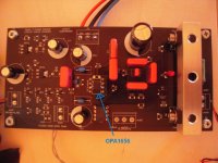
I've put the OPA1656 into my PEARL 3 - boards. Sounds really good. Better than the OPA2134?
Difficult to say. They both sound really good in this circuit.
The OPA1656 is SOIC-8 on a DIP-8-adapter - runs hotter. I've measured around 35° - 38° C on the
OPAmp. Opamp driven into ClassA.
Cheers
Dirk")
I've put the OPA1656 into my PEARL 3 - boards. Sounds really good. Better than the OPA2134?
Difficult to say. They both sound really good in this circuit.
The OPA1656 is SOIC-8 on a DIP-8-adapter - runs hotter. I've measured around 35° - 38° C on the
OPAmp. Opamp driven into ClassA.
Cheers
Dirk
Attachments
Hi Dirk,
When trying the excellent OPA1656 in various set ups I found that it did not benefited from being driven into Class A, which made me wonder as most Op amps I had tried so far rather did (the good old AD825 responded enormously to that tweak for example). Note it wasn't detrimental to the sound either, or perhaps in a very negligeable way (I didn't give it more time TBH).
When asking John - the designer of the chip - about this, he replied that in fact the OPA1656 already benefited from some internal tweaks (forgot about it exactly) that were equivalent to forcing it into Class A / biasing it into Class A. So other than forcing it to run hotter nothing soundwise had to be expected from Class A biasing for OPA1656.
Just for info and again congrats to your build!
MFG
Claude
Hello Claude,
thanks for the great infos! Perhaps other builders can also benefit from such good information?
I will try some other OPAmps. But one of the next steps will be to put that PEARL 3 into a 'house'.
It is still 'living' on the wooden board. Shame on me!
Greets
Dirk
thanks for the great infos! Perhaps other builders can also benefit from such good information?
I will try some other OPAmps. But one of the next steps will be to put that PEARL 3 into a 'house'.
It is still 'living' on the wooden board. Shame on me!
Greets
Dirk
I notice that 6 volt, 4.5 ampere-hour, sealed lead acid batteries are offered for sale (according to Google) at prices around USD 7.00 per piece, plus shipping. Three of them in series give +18V and three more give -18V, plenty to run Pearl 3 for 20+ hours between recharge events. For USD 42.00 plus shipping.
It seems you can achieve even lower dollars-per-watt-hour if you buy 12V SLAs, but now you've got plus and minus 24V to deal with. Dropping that down to plus and minus 18V while adding zero nanovolts of additional noise, might turn out to be difficult in practice.
It seems you can achieve even lower dollars-per-watt-hour if you buy 12V SLAs, but now you've got plus and minus 24V to deal with. Dropping that down to plus and minus 18V while adding zero nanovolts of additional noise, might turn out to be difficult in practice.
Won’t make any difference at all. The raw PSU uses a 15Watt (well, VA, but still…) transformer, the regulators can source at least an amp, and generally the circuit pulls 60mA/channel. So the power supply has massive amounts of excess capacity.
Also, the J112 in the output section is there to pull additional current from the opamp, which will help the circuit more into it’s linear region, which smooths out the upper harmonics if you’re looking at it with FFT or similar.
Anyway, whatever current your opamp of choice will consume, Pearl 3 is ready, willing, and able to use it.
@6L6
re the "bags" of excess capacity...
What exactly are we buying with these large transformers then?
Better regulation?
More capacity to throw away to get to the working voltage?
(I struggle with this in rationalising the voltage I can source versus the voltage I need for the circuit)
enquiring minds...

Do we think some will get mad and by expensive foil resistors for the 47k input resistors like this type?
https://www.hificollective.co.uk/sites/default/files/charcroft_datasheet.pdf
It has 5mm leg spacing so will not fit very well.......needs to look nice also......
I would stay away from the foil resistors. Best case they are are very expensive for 0 benefit.
For a given R resistor distortion is a function of applied voltage squared, PPM T.C.R. and thermal mass or weight.
From my testing, select the largest and lowest PPM thin metal film resistor that will fit on the PCB for lowest distortion and noise.
Given the choice between high thermal mass and lowest PPM go with the larger size resistor.
This is the 47k input resistor that I selected, it fits on the PCB.
https://www.mouser.com/ProductDetail/Vishay-Dale/CMF6047K000BEBF?qs=A%2B/NCR0PvNUgR9U4flCE3A==
Thanks DT
@6L6
re the "bags" of excess capacity...
What exactly are we buying with these large transformers then?
Better regulation?
More capacity to throw away to get to the working voltage?
(I struggle with this in rationalising the voltage I can source versus the voltage I need for the circuit)
enquiring minds...
Large transformer? Too much voltage?
I don’t understand your question.

Last edited:
well, the description talks about transformers sized from 12 to 25VA.
you say they all can provide enough energy.
so... why not a 6VA?
wrt the voltage, transformers are made in increments of output voltage, right?
too small won't function at all, but if the next increment up needs significant stepping down... then maybe the VA needs to be higher to have voltage to throw away.
I wasn't talking about physical size per se.
- Home
- Amplifiers
- Pass Labs
- Pearl 3 Burning Amp 2023