If I use an UDP3 PSU, should I keep the 7815/7915 on board regulator ?
from post #1 in the UDP3 thread:
Instead, UDP3 uses ferrite beads and several cascaded filters (one of which is a two-pole LRC filter), to achieve excellent noise reduction even at radio frequencies. The big idea is: provide Pearl 3 with a pair of low-ripple, low-noise, RF-free raw DC voltages, and let Pearl 3's onboard voltage regulators do their job, when given pristine inputs.
The UDP3 outputs plus and minus nineteen volts (approximately! remember, UDP3 is not a regulator), which the 7815 and 7915 voltage regulator IC on the Pearl 3 boards, then reduce to smooth and regulated plus and minus 15 volts.
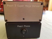
Just before I ship it back... this is the V2 of the P3. This one has all SMD... hence the "Super Mega Deluxe". i haven't opened it, but I figure the boards must be stacked inside.
Mine is the v3, and that one is made for op amp rolling... Note how I use thumb screws and spacers to make room for the big Bursons.
Mine is the v3, and that one is made for op amp rolling... Note how I use thumb screws and spacers to make room for the big Bursons.
Attachments


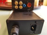
Still at this final wrap up...Power supply is now working as it should, even though the on-off symbols on the schurter were reversed(!), now fixed with a bit of fancy graphics and a reprogramming of my brain to forget which way On should be LOL. .
Started testing the phono stage. I'm getting 19.36 on + left side, and -12.71 on -. On the right side, 19.49 on +, and -12.74 on -. Thought they were supposed to be the same or darn close?
R27 left is 1.67, and R27 right is 2.2.
Seems like something might be awry here....I'm not seeing any bad solder joints (of course, my eyesight is even worse than it was 4 weeks ago. This is the speed at which certain blindness can attack. I think I've got less than a year of sight left at this rate). I can try to take some pics tomorrow if necessary, but not sure what would be important to photograph. Help, as always, is greatly appreciated!
I'll try to get some pics tonight, though I've been given time limits on hobbies by the wonderful partner, and i think there are plans made...
It would seem that the problem would lie in my umbilical (a phrase never before uttered in the history of the english language), as the rail voltages are spot -on coming off the power supply board, and wacky as they go into the phono boards.
It would seem that the problem would lie in my umbilical (a phrase never before uttered in the history of the english language), as the rail voltages are spot -on coming off the power supply board, and wacky as they go into the phono boards.
I apologize for the quality of the pictures, and most likely the sloppy soldering: I'm losing my sight quite quickly, and along with the disintegration of my fine motor skills in my fingers, I am really running out of time to get this right (or at least workable). Please let me know if you see anything that looks awry!Rail voltages seem wonky. Please post pix of the power supply box and the phono box.

Hello.
I would check the marked ones, reflow everything, and partly clean all boards.
Sorry about your eye sight, i know what thats like , yesterday i had to desolder a multi turn pot, had to use stereo microscope, it took 30 minutes, 5 years ago that would have been 5 minutes
I would check the marked ones, reflow everything, and partly clean all boards.
Sorry about your eye sight, i know what thats like , yesterday i had to desolder a multi turn pot, had to use stereo microscope, it took 30 minutes, 5 years ago that would have been 5 minutes
Thankyou both. I'll give those a go...
Regarding cleaning the boards, i use one of those spray cleaners...doesn't always seem to get the flux off well without concentrated scrubbing. Is there a proper way to do it?
The eyes fail me terribly here. Even 3 months ago i could see the "fine print" clearly. Well, with a little belp from a magnifier. Now i can't even with a dental loop. The speed at which it is dereriorating is unnerving, as not only will i shortly need to have someone else put the stylus to groove, but as an architect I'm going to have to reimagine how I can continue with my life's work.
Ideally i get this Pearl 3 and an Aleph J done and can enjoy great music!
Thanks again for taking the time to help out!
R27 left is 1.67, and R27 right is 2.2.
Looks like you got a good matched octet of the 170s. What Idss did you measure for those or were you provided with? You need them as low as practical.Started testing the phono stage. I'm getting 19.36 on + left side, and -12.71 on -. On the right side, 19.49 on +, and -12.74 on -. Thought they were supposed to be the same or darn close?
From highlighted pics above in #5347, R15 and R18 share a trace at that point anyway. No worries.
If the LED works, I wouldn't give it too much thought.
First I respect that your vision isn't in top form. I have vision trouble myself. Thankfully, mine is only a slow age-related decline. I am so sorry to hear of your situation. So, my attempt is to provide what I'd do to only need to fix it once vs. need to iterate.
You have too much current running through the Op-amp. I ran into a similar situation with my build (K170 also, but my Idss was likely much lower). So, my rails were mismatched a bit, and the PSU was sagging on the negative rail.
As soon as I set the current to specs through the op-amps by altering R27, voila.
So, unless others have a more plausible thing to try... what I'd do first is consult the exceptional build document, which says:
"U1 Bias notes. Remember Ohm’s Law V = I * R Therefore, I = V / R Assume 220R resistor in R27 position. V = I * R = 2mA * 220R = 0.44V and V = I * R = 5mA * 220R = 1.1V If you measure between 0.44V and 1.1V with R27 = 220R – you’re good to go."
You have double the maximum current through the right, and you're ~50% over on the left with your existing 220R in place for both channels.
Choose a target. Why not smack in the middle at about 3.5 mA or close. That will possibly prevent you from needing to change that part twice if you don't get it low enough.
After you swap out R27 for both channels, see if your PSU starts to play nicely. If not, look further.
Related, but separate - If you know the Idss of the K170s you used, others may have you take a look at adjusting R10 to reduce the current through the parallel JFETs. That's a tad beyond my personal expertise to give direct guidance. Me, I'd just measure the current though them and toss in a source resistor to get it where I wanted, but ... it's best to consult an actual expert that knows the circuit to see if that may help vs. a solder slinger like me.
Cheers,
Patrick
Hi Patrick,
The idss of the Todhibas is 8.5mH. R4 through R7 were changed to 22r from 10r.
I need to learn more about how all this stuff really functions. I know that's a basic formula, but i'm not sure i understand how it actually works. I've got a 315r 3watt in the drawer i could try...
The idss of the Todhibas is 8.5mH. R4 through R7 were changed to 22r from 10r.
I need to learn more about how all this stuff really functions. I know that's a basic formula, but i'm not sure i understand how it actually works. I've got a 315r 3watt in the drawer i could try...
No........ Those Toshiba´s are 8,5 mA idss..... not mH. Not to worry. With R4 to R7 = 22R you have nothing to worry about.
And NO........ Replace R27 with 680R/½w. 0.5w resistor for R27 is more than fine. And expect the voltage over R27 to rise a little
when increasing the resistance. I ended up in one of my builds with R27 = 815R to get 3.9mA 😉
And NO........ Replace R27 with 680R/½w. 0.5w resistor for R27 is more than fine. And expect the voltage over R27 to rise a little
when increasing the resistance. I ended up in one of my builds with R27 = 815R to get 3.9mA 😉
Thanks for the correction!! I often find myself typing things out of habit...😉
Wasn't thinking 3 watt resistor because it was necessary, but because i have a bunch! Lol. Now you're making me place another Mouser order!
Much appreciate the assist here!!
Wasn't thinking 3 watt resistor because it was necessary, but because i have a bunch! Lol. Now you're making me place another Mouser order!
Much appreciate the assist here!!
Last edited:
Regarding cleaning the boards, i use one of those spray cleaners...doesn't always seem to get the flux off well without concentrated scrubbing. Is there a proper way to do it?
The eyes fail me terribly here.
I bought, from somewhere online, just some MG Chemicals 99% isopropyl alcohol and put it into a spray bottle. Yes it took a few tries, and a bit of brushing, but the boards came out very clean. Unfortunately, it's a bit of work but take your time.
As for failing eyes, I personally suggest a Donegan OptiVisor. If you get a headset like this you can change out the lenses depending on how much magnification you need. They also use glass lenses instead of plastic, which is great for soldering. Just a thought. I'm enjoying mine.
https://www.amazon.com/dp/B0015IS6K2?ref=ppx_yo2ov_dt_b_fed_asin_title&th=1
I have that same cartridge, and also the Pearl 3. Can you please explain that resistor tricks function ("with the 300uV") and why please. If It would be applicable in my system, that would be appreciated.Absolutely no need to buy a SUT with the Pearl-3.
I know. I have Silk Audio´s MC-220A, Sowter and Cinemag´s.
As much as I have preferred them with different riaa´s, they are not in use now.
The MC stage in Pearl-3 is unusually quiet, and has more than enough gain to satisfy even the lowest output MC´s.
I even reduced the R9 2,2K to 1,2K to go with the 300µV AT-33PTG/II. Still more than enough gain and dead quiet.
Russellc
- Home
- Amplifiers
- Pass Labs
- Pearl 3 Burning Amp 2023