simulations of the basic design revisited
OK, after a long break, I started again. This time, I used FEMM, as I couldn't figure out how to plot the normal component of B in Maxwell 9SV.
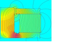
The simulations agree qualitatively, but I am getting a maximum B of 0.86 T in the gap compared to about 0.95 with Maxwell. This could be due to the material constants for 1010 steel and Ceramic 8 being different in the FEMM package, or due to slighly different tolerances in the mechnical layout I entered.
Here's the field simulation from FEEMM
OK, after a long break, I started again. This time, I used FEMM, as I couldn't figure out how to plot the normal component of B in Maxwell 9SV.
The simulations agree qualitatively, but I am getting a maximum B of 0.86 T in the gap compared to about 0.95 with Maxwell. This could be due to the material constants for 1010 steel and Ceramic 8 being different in the FEMM package, or due to slighly different tolerances in the mechnical layout I entered.
Here's the field simulation from FEEMM
Attachments
and now calculated BxL
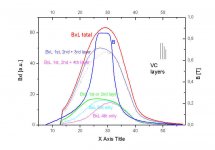
Up to now, I had only B curves. I exported those to excel and did a moving integration to obtain BxL.
The initial reason for starting this thread was the discovery that the windings were asymmetrical. This is indicated graphically in the top right corner of the plot:
The first two windings are 17 mm long, the third is only 15.5 mm long, and the forth is 14 mm long.
The plot shows the B curve in blue and in units of T (right hand scale).
The solid red curve is the total BxL of all four layers. The solid green curve is the BxL of the first or second layer.
You can see that the full length 1st and 2nd layers have a pretty broad plateau that is slightly tilted to the right (i.e. outwards cone movement). The third layer is narrower and has its maximum to the right, and the fourth layer is even narrower and further shifted.
The sum of all four layers hence is narrower (pointier) than for a standard VC that has layers of uniform length.
What this will do:
- reduce second harmonic distortion if the centering is perfect
- increase third and fifth harmonic distortion
- increase second harmonic distortion for small excursions of rest position is not centered about the peak of the red curve
- increas even order distortion for large excursions (the flanks of the red curve are more asymmetrical than the green curve's)
=> Although the current HDS drivers maintain essentially the same motor design (there is a very slight undercut of the pole, but by less than 0.5 mm), they now use only standard voice coils, and this is easy to understand by looking at the calculations.
It also means that I will give up on attempts to symmetrize the BxL curve without rewinding the VC. It seems to be possible to symmetrize the curve, but the price to be paid is a pointier plateau for small excursions.
Attachments
- Status
- This old topic is closed. If you want to reopen this topic, contact a moderator using the "Report Post" button.