Why not use a discrete classA buffer - single transistor emitter follower and constant current source (2 transistor)? The classA current should be enough to drive the feedback network plus the output RC.
you can also use "old" buffers also, such as HA5033, HA5002, etc.
look in some old headphone threads for old part numbers.
you can often pick them up cheap at surplus mail order stores.
but watch out; there are some that don't have built in current limiting, so you have to be careful with the design.
mlloyd1
look in some old headphone threads for old part numbers.
you can often pick them up cheap at surplus mail order stores.
but watch out; there are some that don't have built in current limiting, so you have to be careful with the design.
mlloyd1
Last edited:
I have made a pcb for this design.
Hi peranders. Your link no longer works. Is it possible to get a new link, or perhaps for you to email your artwork to me?
--dwf
Good afternoon Peranders
i'm also interested in your circuit
Originally Posted by peranders View Post
I have made a pcb for this design.
Best regards
Jean Claude
i'm also interested in your circuit
Originally Posted by peranders View Post
I have made a pcb for this design.
Best regards
Jean Claude
Hi
Can some one explain to me what is the circuit with Jfet for (in the RIAA schema on the LT1115 datasheet)?
Thanks
Can some one explain to me what is the circuit with Jfet for (in the RIAA schema on the LT1115 datasheet)?
Thanks
And is overkill as a simple resistor would do the job (which might not really need doing anyway)It is there to draw a small bit of current to put the output stage in class A
The LT1010 buffer also looks like overkill - they are just trying to sell more LT parts in this schematic I think - the LT1115 can drive 600 ohms all by itself, a 150mA current buffer isn't required for a line level audio signal in any reasonable scenario I reckon.
Also the LT1115 chip is a fair bit noiser for a MM cartridge than an NE5534A as its current noise is dissappointing (not unusual for a chip with ultra-low voltage noise). This circuit is best matched for MC inputs where the source impedance is low. For MM a JFET opamp is usually a good choice as the current noise issue dissappears - amongst bipolars the 5534A still pretty much wins still for low current noise.
Some folks would also be unhappy about the lack of a blocking capacitor on the input too.
For MM a JFET opamp is usually a good choice as the current noise issue dissappears - amongst bipolars the 5534A still pretty much wins still for low current noise.
OPA2210 is bipolar and beats NE5534A on both voltage and current noise. Yes the typical 1kHz spot current noise is the same but its 1/f corner is considerably lower so integrated out its quieter. Its rather a lot more expensive though.
It is there to draw a small bit of current to put the output stage in class A
Thank you. I suppose you mean the op amp's output stage?
LT1115 MMMC RIAA
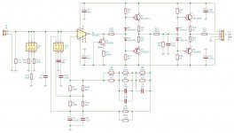
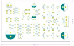
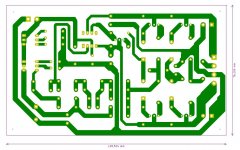
I am about to building this appnote-amplifier with a friend of mine. For now, I have drawn the schematic and made a layout in KiCAD.
Schematic:

Layout:

PCB:

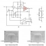
The LT1010 buffer is replaced by a discrete buffer actually claimed to be slightly better in another appnote by LT:

I included another buffer at the outut, but I suspect it to be redundant.
The PCB is quite large, sorry about that! 🙂
I am about to building this appnote-amplifier with a friend of mine. For now, I have drawn the schematic and made a layout in KiCAD.
Schematic:

Layout:

PCB:

The LT1010 buffer is replaced by a discrete buffer actually claimed to be slightly better in another appnote by LT:

I included another buffer at the outut, but I suspect it to be redundant.
The PCB is quite large, sorry about that! 🙂
Just a few notes on the schematic:
Components for input loading are chosen quite arbitrarily, and should be changed for the pick-ups used.
Components marked as aaa, bbb, ccc, xxx, yyy, zzz respectively, are added in case one wants to make serious RIAA component matching.
The appnote mentions that the 2N4304 is not critical. Any FET or constant current device delivering about 2mA wil do.
rsavas:
Sorry, shame on me!
Are you referring to the LT1010 substitution or anything else in particular?
Sorry, shame on me!
Are you referring to the LT1010 substitution or anything else in particular?
It is not shameful to not simulate but it is also a good way to verify the operation as intended of any part of the design. Just a suggestion
You are right, it maybe time to learn LTSpice....!
Since the design is cloned from the LT appnote, I thouhgt the minor change from LT1010 to a discrete buffer would be trivial.
Two ways to find out: Spice it or build it....
Since the design is cloned from the LT appnote, I thouhgt the minor change from LT1010 to a discrete buffer would be trivial.
Two ways to find out: Spice it or build it....
I am about to building this appnote-amplifier with a friend of mine. For now, I have drawn the schematic and made a layout in KiCAD.
Schematic:
View attachment 992819
Layout:
View attachment 992820
PCB:
View attachment 992821
The LT1010 buffer is replaced by a discrete buffer actually claimed to be slightly better in another appnote by LT:
View attachment 992822
I included another buffer at the outut, but I suspect it to be redundant.
The PCB is quite large, sorry about that! 🙂
you can very easily bootstrap the opamp into class A with a single resistor - no need for the JFET or a resistor to one of the rails.
Here is how to do it
Class A Buffering the Correct Way
- Home
- Source & Line
- Analogue Source
- Phono preamp from the LT1115 datasheet