it would be better if we were able to attach, but inline in text body; this is much more useful than just in a group at the bottom, particularly for tutorials. presently, unless things have changed; I think the only way you can do that is if linked from an external host. if attached afaik it always must be in a group at the bottom of the post. so if there could be a limit of file size/visual size, but also allowing inline images this would be ideal IMO
it's easy to implement same size [KB] restrictions for both attached and linked pictures , when polishing forum software ; in that case bigger pic files can be automatically just shown as active text links , instead as pics shown inline in post's body
not easy for me , but certainly for guys doing the job
anyway - I always prefer attached pics , or at least linked to place which I'm directly controlling
which was exactly the case with PsykoK's pics (own web site) , except last one (euphonia forum)
Last edited:
ZM -
If you wait, the board will automatically resize the pics and present a smaller thumbnail. It takes usually a couple of hours. Then you can still click into the really big pics if you care to.
It always seems to do that to my photos, but I try not to post anything wider than about 600 or so.
If you wait, the board will automatically resize the pics and present a smaller thumbnail. It takes usually a couple of hours. Then you can still click into the really big pics if you care to.
It always seems to do that to my photos, but I try not to post anything wider than about 600 or so.
Last edited:
Hi Marra,
You know the wood working was the easy part.
Dovetail are not hard to do if you are patient.
Alex
well in that case, i hate u.
im kidding. very nice. something to strive for, on my end.
wow, i wish i could do that.
Pass DIY Addict
Joined 2000
Paid Member
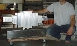
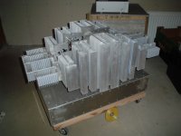
....my unfinished amplifier , missing some parts
Alex.
Alex - In the first image of your chassis, I'm looking at the shiny square next to your power supply caps that looks like a bridge rectifier. This method of mounting the rectifier will cause it to overheat and fail. The case of the rectifier is metal and needs to be attached to a heat sink in order to dissipate heat. It may be that you have already purchased a sink to attach to the top of your rectifier, in which case there are no worries.
But, as pictured, you are set up for a problem in the near future. You might even want to move the rectifier off of this board and directly attach it to one of main sinks for your chassis...
Eric
Hi Marra,
You know the wood working was the easy part.
Dovetail are not hard to do if you are patient.
Alex
You haven't seen me let loose with a tenon saw
You haven't seen me let loose with a tenon saw
When I use one its a TENDON saw!
Skill I don't have it
Today I start using my new amp;
I allready showed it on a separate thread but I posted a preview here a while ago.
In the future I will give it a nice finish
here; 8 Channel Amplifier
and here; http://www.diyaudio.com/forums/pass-labs/205889-several-alephs-one-big-case.html
I allready showed it on a separate thread but I posted a preview here a while ago.
In the future I will give it a nice finish
here; 8 Channel Amplifier
and here; http://www.diyaudio.com/forums/pass-labs/205889-several-alephs-one-big-case.html
Attachments

F5, F4 and BA3FE
Hi, it took me 2 years to finish this 3 projects.
Started with the F5, it was the hardest but it grew easier as I gained more experience.
The hardest part was building the chassis.
Took many tips offered in the forum to implement.
Thank you Nelson and fellow diyers who replied to my queries. It has been fun and they really sound good.
 F5
F5
F4
F4 with BA3 FE
Hi, it took me 2 years to finish this 3 projects.
Started with the F5, it was the hardest but it grew easier as I gained more experience.
The hardest part was building the chassis.
Took many tips offered in the forum to implement.
Thank you Nelson and fellow diyers who replied to my queries. It has been fun and they really sound good.
An externally hosted image should be here but it was not working when we last tested it.
F5An externally hosted image should be here but it was not working when we last tested it.
F4An externally hosted image should be here but it was not working when we last tested it.
An externally hosted image should be here but it was not working when we last tested it.
F4 with BA3 FEHi, it took me 2 years to finish this 3 projects.
Started with the F5, it was the hardest but it grew easier as I gained more experience.
The hardest part was building the chassis.
Took many tips offered in the forum to implement.
Thank you Nelson and fellow diyers who replied to my queries. It has been fun and they really sound good.
Those are very nice and clean builds (I am aspiring to an F4 one day as a winter amplifier... after the rest of my projects clear up). It must have been a challenge to do this where you are already as space is limited and not everyone there has garages and workshops like we do in the suburbs.
Do you have tops to go with those? Did you go naked (like they are in the pictures), clear, painted, vented, or unvented?
Aleph J, nearly done
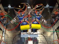
I am nearly done finishing my first power amp build, an Aleph J. Enclosed a photo.
I hope to be able to test the PSU tomorrow or the day after. I have bought a cheap 3KVA Variac, but it was delivered without a power cord and the plug is different from a normal IEC power plug. As soon as I get the right one I can slowly bring up the power and hope I got everything right.
I could not use the Peter Daniel PSU boards because the 33000uF/50V caps I had bought did not fit. I hope the PSU resistors will be OK like this.
The unconnected red and green wires are V+ and V-. I thought it best to leave these unconnected from the amp boards until I verify that the PSU works correctly!
In order to make sure my ground star point was not directly connected to the chassis, I mounted it on a piece of plastic that itself is raised about 2 inches above the chassis. There is a wire from the star ground to a CL-60 and then to chassis. Safety earth is of course directly connected to the chassis.
Thanks so far to everyone (especially Nelson Pass!) for your help in making this possible!
I am nearly done finishing my first power amp build, an Aleph J. Enclosed a photo.
I hope to be able to test the PSU tomorrow or the day after. I have bought a cheap 3KVA Variac, but it was delivered without a power cord
and the plug is different from a normal IEC power plug. As soon as I get the right one I can slowly bring up the power and hope I got everything right.I could not use the Peter Daniel PSU boards because the 33000uF/50V caps I had bought did not fit. I hope the PSU resistors will be OK like this.
The unconnected red and green wires are V+ and V-. I thought it best to leave these unconnected from the amp boards until I verify that the PSU works correctly!
In order to make sure my ground star point was not directly connected to the chassis, I mounted it on a piece of plastic that itself is raised about 2 inches above the chassis. There is a wire from the star ground to a CL-60 and then to chassis. Safety earth is of course directly connected to the chassis.
Thanks so far to everyone (especially Nelson Pass!) for your help in making this possible!
Attachments
A bulb tester is a better way to bring the "untested" wiring around the transformer and PSU up to full voltage.
The bulb automatically lights if the transformer draws too much current.
Using a Variac you, the operator, has to monitor the voltages and currents and smells around the circuits. You cannot do all of that properly and "in time" to prevent damage.
Remove all that wiring and replaced with twisted pairs.
- Home
- Amplifiers
- Pass Labs
- Pictures of your diy Pass amplifier