When I saw Papa's new SIT muffs on the street I couldn't resist and had to give one whose features I had not seen before a thorough workout. After stimulating that special muff (oops, I meant simulating, but you knew that), I recommend that you give it a try too.
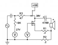
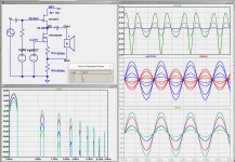
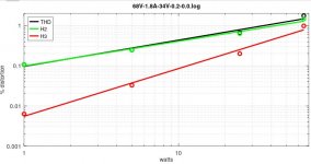
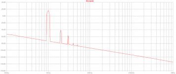
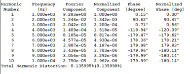
Papa's SIT/NFET mu follower follower is shown in the last schematic of the Nelson Pass paper “BAF 2022 SIT Power Amplifiers” https://www.diyaudio.com/community/attachments/baf-2022-sit-amplifiers-pdf.1101782/, shown in the first image below. The paper shows circuit parameters and performance results for the PFET muff. When I simulate the NFET version of the muff using the same parameters I get the essentially the same results. The second image shows the circuit, power spectra, and waveforms at 1W, 5W, 25W and 45W into an 8R load. The power spectrum has a nice rolloff characteristic. The idle power dissipation is 60V*3A=180W per channel.
In this thread I will show simulation results using variety of parameter combinations using the circuit shown in the second image.
Attachments
Last edited:

Can we improve the performance of the muff for given choices for the SIT, NFET, speaker load?
The mu follower behavior is dominated by the following parameters, all of which interact in ways that modify the distortion spectra and other characteristics:
A very nice result!
The mu follower behavior is dominated by the following parameters, all of which interact in ways that modify the distortion spectra and other characteristics:
- SIT/NFET - Choice of SIT and NFET
- Vds(SIT) - Drain to Source voltage of the SIT - controlled by VgSIT voltage
- Iq - Quiescent bias current - controlled by VgNFET voltage
- R1 - NFET degeneration resistor
- R2 - Mu follower gain resistor
- Rload - Speaker load impedance
- V+ - Rail Voltage (note 1) - doesn't much affect performance until clipping.
- Lower distortion - Shape of distortion spectra -
- Jean Hiraga criteria? https://audioxpress.com/article/Musicality-and-Distortion-A-Conversation
- Higher power output
- Lower power consumption
- Less expensive to build
A very nice result!
Attachments
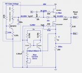
But, the parameters Iq=1.8A, R1=0R, R2=0.2R result in a voltage drop across R1+R2 of only 0.36V, far less than required by the optocoupler servo. There are variants of the optocoupler servo that can reduce the sense resistor voltage drop requirment, but I chose a different approach, shown next.
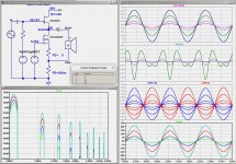
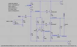
Because the Nmuff circuit topolopy, the input to the bias current servo (the top of resistor R1) has a voltage near ground, and the output of the servo is the gate of the NFET, which also has a voltage near ground. This makes it easy to implement a bias servo with thee differential amplifier circuit shown below. The voltage across the variable resistor Rx adjusts the bias current. This servo has considerable gain and excellent stability to variations in rail voltage and temperature, as well as output signal power.
The simulations results are essentially the identical to those of the previous post. The circuit details are shown below.
What is not to like about this special muff?
Attachments
Nope, but I am working on a PCB layout that will be a plug-in replacement for the SIT3X output stage PCB. Since I built two version of the SIT3X, I can use the front-end, power supply, and chassis of one of them.got it on bench?
There is an official (and complicated) Spice Model on the Littlefuse IXYS website: https://www.littelfuse.com/media?re...8e-b41b-6326d4f4e8cd&filename=ixfn140n30p.zip. However that model was intended for uses other than audio amplifiers.Nice!
Could you provide IXFN140N30P model?
I did bench measurements of several IXFN140N30P FETs and generated a level-1 Spice model that seems to be pretty good for the range of currents and voltages I needed.
.model IXFN140N30P VDMOS(nchan Vto=5.0 Kp=30.0 Lambda=3.3m Rs=2.2m Rd=0.17 Rds=1e7 Cgdmax=4nf Cgdmin=50pf a=0.35 Cgs=1250p Cjo=3000p m=0.75 VJ=2.5 IS=4.0E-06 N=2.4)
Attached is an LtSpice zip file for those who want to run simulations of the SIT-Nmuff. This is the simple version of the simulation using voltage sources rather than the differential amp servo.
Unzip the file into a directory and load load SIT-Nmuff-simp-1.asc into LtSpice.
Warning: I have not tested this in a "virgin" LtSpice environment without some of my library customizations.
Unzip the file into a directory and load load SIT-Nmuff-simp-1.asc into LtSpice.
Warning: I have not tested this in a "virgin" LtSpice environment without some of my library customizations.
Attachments
But that schematic now has -32V on the Out- and Out+ varies -32V +/- signal.
The "2022 BAF SIT Amplifiers" paper shows the SIT drain connected to ground and the R2 (R4 in your schematic) at the bottom connected to ground. The Out- connection is at about 0.6V, and Out+ varies +0.6V +/- signal.
The "2022 BAF SIT Amplifiers" paper shows the SIT drain connected to ground and the R2 (R4 in your schematic) at the bottom connected to ground. The Out- connection is at about 0.6V, and Out+ varies +0.6V +/- signal.
I knew nobody like any voltage on speaker. Then a +/-32V power supply could do the trick.
I was more concerned with exposed live DC. If you are well grounded and you touch either the terminals on the amp or on the speaker, it would be a shock.
That would work for the PFET version of the muff as long at 32V is at the desired Vds for the SIT, and the +32V supply is sufficiently quiet. If a cap. multiplier is used to get a very quiet V+ supply, it can be made adjustable in voltage drop. Then you could use +/-36V supplies with some range of adjustment on V+. If you are really careful you might not need the capacitor output.I knew nobody like any voltage on speaker. Then a +/-32V power supply could do the trick.
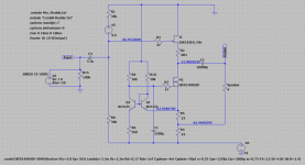
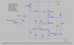
I have solved the issue with the NFET muff Out- being "hot". You can float the power supply negative side V- and ground Out-. With a minor modification to the BAF 2022 SIT AMP gain stage the circuit behaves the same either with V- at ground or Out- at ground.
Below is the schematic, with the idealized Nmuff output stage.
Below is the schematic, with the idealized Nmuff output stage.
Attachments
- Home
- Amplifiers
- Pass Labs
- Pimping Papa's SIT muffs