I am not concerned about the shock hazard. In my NFET muff design, the NFET degeneration resistor (R1) can be zero. If Out- is accidentally connected to ground then the current through the SIT and the NFET can be very large and destructive to the devices.~42v dc is considered the threshold for what is safe for an exposed voltage. Above that is considered high voltage. This is from the standpoint of personal shock hazard.

I have studied and simulated a variety of PFET and NFET muff alternatives and have arrived at one that simulates well and whose topology is quite simple:
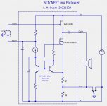
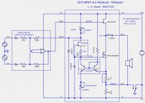
- SIT/NFET muff
- A single JFET constant current source (CCS) for SIT Vds and quiescent idle current circuits.
- SIT Vds generated by voltage drop across a resistor connected to the CCS.
- Idle current controlled by a circuit having the topology of a current mirror.
- Modified version of the Statis front end.
Attachments
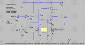
Here are some simulation results.
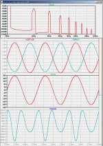
- The first image shows various waveforms and the spectrum for 1 Watt, 1 kHz, 8 Ohm load.
- The second image is the same for 25 Watts.
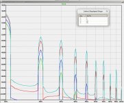
- The first image shows the spectra for 1W, 5W, 25W and 45W.
Attachments
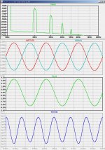
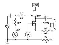
The power supply voltage is 64V and the SIT operating point is at about 1,8A bias and Vds=32V. The total power dissipation is about 120 Watts per channel.
Due to the role of the JFET CCS, the SIT operating point remains very constant with changes in the power supply voltage. The bias current is stable with temperature changes because the base to emitter voltage (Vbe) of the pair of bipolar transistors in the "current mirror" cancel.
The output power remains class-A up to 50W into 8 Ohms. Notice that resistor R1 is a dead short (0 Ohms) and R2 is 0.18 Ohms. Thus the voltage seen by the bias servo is only 330mV. Because R1 is eliminated, the third (and higher) harmonic distortion is reduced.
With a 4 Ohm load, the output continues to be negative phase second harmonic and the damping factor is around 32. With only 1.8A bias, the output is current limited at about 35W into a 4R load before leaving class-A. If you really want more power into a speaker with lower than 8 Ohm impedance, one can raise the bias current and, if needed, lower the rail voltage to preserve the power dissipation level needed for your heat sinks.I have been tracking and find this all very interesting. I am wondering how the circuit behaves for 4 ohm load? And what would the ball park damping factor be?
Have seen 72v dc projects and more. If 42v dc is a problem the best is to do nothing and no risk.~42v dc is considered the threshold for what is safe for an exposed voltage. Above that is considered high voltage. This is from the standpoint of personal shock hazard.
This is interesting, In stead of using a SIT with it's tube like behavior
could the MUFF curent source be used with a big power triode say
the 6c33c. The 6c33c can be used up to about 600ma but for safety
perhaps limiting it to 400ma might be better but that only works out
to ~1W but if I was able to use the MUFF wouldn't that let me have
~4W ? But the 6c33c has cathode output resistance of ~ 27 ohms what
effect would the MUFF have on the output resistance.
everything is possible
but - what are the criteria and are they met in final iteration?
I mean - basic idea of (some) Greedy Boyz - why SIT - to get some basic virtue of toobz, gaining some virtues of sand, while avoiding substantial part of complexity of toobz
And now, you want toob
Anyhow, completely valid approach ....... you just need to find proper example or to devise your own
This is interesting, In stead of using a SIT with it's tube like behavior
could the MUFF curent source be used with a big power triode say
the 6c33c.
I am not very knowledgeable about the tube (valve) world, but as I understand it, there are a lot of designs which combine triodes with mosfet current sources and mu followers, but they generally rely on output transformers. Look at tubecad.com. There might be exceptions, but they have low output power.

- Home
- Amplifiers
- Pass Labs
- Pimping Papa's SIT muffs