No. The varistor just clamps extremes of transient pulses that may randomly appear. Many SMPS don't even bother. These are transients of durations in microseconds.With the varistor removed, won't the input voltage at the diodes be higher than expected?
That doesn't compute unless heat from desoldering it randomly heals it up 🙂If I remove L101, the short is gone, if I jump it, the short is gone.
Now that doesn't compute either unless the fuse was a fast blow.I have a DBT but I've been using it with a 60w bulb. it lights the bulb but sill blew the 2a fuse.
On 120 volt mains a 60 watt bulb pulls 0.5 amp. I=W/V
And just to be clear on this, you are putting the bulb in series with the incoming mains supply, in other words essentially in place of F101?
Edit... you must be certain that you understand all the safety implications of working on this.
You mean PC102. That is an 'opto isolator'used for feedback to regulate the output voltage. It provides 'galvanic isolation' between the primary and secondary side of the supply because the primary side is always live. and there must be no path to the secondary side for safety.What I can't test is the IC .
Is it odd that they rectify the power before the transformer?
The transformer is driven at very high frequency by the electronics which is why it is so small (higher freq is much more efficient than 50/60Hz). These supplies also provide constant output voltage over a wide range of input voltage such as 90 to 265 volts AC input with no adjustment required.
It looks to me like the power comes in through the fuse, to Z101, R101, C101, then through L101, C103/104, and to the rectifier diodes, from that point on its DC current. 120V AC is what goes right to the diodes.
Most of the receivers and such I've worked on the power goes to the transformer first, then through the rectifier(s), and then to the various boards.
This whole power supply is hot all the time that its plugged in.
If I jumper L101, nothing changes, if I remove it and jump it, I get 120v to the IR4005 diodes, and power to the transformer.
What I am seeing is that the output volts are high. It appears that the transformer is 120 to 28v, but I'm getting near double the volts on at the ribbon cable on the other end.
The IC I was talking about is the PQ3RD13 at IC202, which I believe is a VR for the low voltage feed.
It calls out 3.3v (I have 6.8v there) and 12v at pins 5 and 7 on the ribbon cable, I have 18.3 vdc there.
With basically ac current going direct to the rectifier diodes, with only R101 and C101 installed, I have 116v at the rectifier and it lights the 60w bulb. I switched to a 5w bulb and it lights full bright as soon as I plug it in as long as the L101 is in place, remove it and it glows but not full bright. The fuse blew after about a minute again. Its a 2a fuse, not fast blow. Its out of the parts assortment I have here, no idea what brand fuses, they're not marked. Its just a bag of 2a fuses in a Tekronix bag.
(the hot side of the ac line goes through the bulb in series with the load.
Lets look at this a different way, if it got 240v to the outlet, what would most likely be damaged?
What still gets me is that the receiver is fine, I played it all day yesterday, and its got 100 hours of use on it since the voltage issue.
If I test L101 across the coils, three of the pins have zero ohms, that means its somehow crossing the incoming current directly
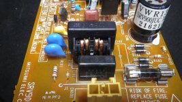
Here's a few more pics, plus the full ps diagram from the manual Showing from the AC in to the ribbon cable out.


Most of the receivers and such I've worked on the power goes to the transformer first, then through the rectifier(s), and then to the various boards.
This whole power supply is hot all the time that its plugged in.
If I jumper L101, nothing changes, if I remove it and jump it, I get 120v to the IR4005 diodes, and power to the transformer.
What I am seeing is that the output volts are high. It appears that the transformer is 120 to 28v, but I'm getting near double the volts on at the ribbon cable on the other end.
The IC I was talking about is the PQ3RD13 at IC202, which I believe is a VR for the low voltage feed.
It calls out 3.3v (I have 6.8v there) and 12v at pins 5 and 7 on the ribbon cable, I have 18.3 vdc there.
With basically ac current going direct to the rectifier diodes, with only R101 and C101 installed, I have 116v at the rectifier and it lights the 60w bulb. I switched to a 5w bulb and it lights full bright as soon as I plug it in as long as the L101 is in place, remove it and it glows but not full bright. The fuse blew after about a minute again. Its a 2a fuse, not fast blow. Its out of the parts assortment I have here, no idea what brand fuses, they're not marked. Its just a bag of 2a fuses in a Tekronix bag.
(the hot side of the ac line goes through the bulb in series with the load.
Lets look at this a different way, if it got 240v to the outlet, what would most likely be damaged?
What still gets me is that the receiver is fine, I played it all day yesterday, and its got 100 hours of use on it since the voltage issue.
If I test L101 across the coils, three of the pins have zero ohms, that means its somehow crossing the incoming current directly
Here's a few more pics, plus the full ps diagram from the manual Showing from the AC in to the ribbon cable out.
Attachments

Yes, the input circuitry to all intents and purposes puts AC line voltage across the bridge. Everything up to that point on the bridge is just for interference suppression.It looks to me like the power comes in through the fuse, to Z101, R101, C101, then through L101, C103/104, and to the rectifier diodes, from that point on its DC current. 120V AC is what goes right to the diodes.
You should end up with rectified mains across C106 which is 170 volts DC for 120 volt mains.
SMPS is very different in how it operates. Conventional transformers use the nice sine wave of the mains at 50/60 Hz to operate. SMPS use a transistor to 'pulse' the much smaller transformer. The transistor controlling the primary (Q101 in yours) is either fully on or fully off. The components across the primary, the diodes, caps and L102 work in conjunction with the resonant frequency of the transformer and help keep the primary current and voltages within limits. A form of resonant tuning, All this runs at perhaps 50 to 100kHz or so.Most of the receivers and such I've worked on the power goes to the transformer first, then through the rectifier(s), and then to the various boards.
The output from the transformer secondaries is a peaky and noisy type of waveform, not a nice sine wave.
Lets look at this a different way, if it got 240v to the outlet, what would most likely be damaged?
The reservoir cap C106 may have suffered.
Q101 would always be favourite but these tend to either fail short circuit or be OK.
I honestly thought this was dead and not working following the voltage incident.What still gets me is that the receiver is fine, I played it all day yesterday, and its got 100 hours of use on it since the voltage issue.
The IC I was talking about is the PQ3RD13 at IC202, which I believe is a VR for the low voltage feed.
It calls out 3.3v (I have 6.8v there) and 12v at pins 5 and 7 on the ribbon cable, I have 18.3 vdc there.
That has to be a 3.3 volt reg looking at the marked voltages. If you have 6.8 volts on the output then the reg would seem to be zapped. Measure directly across C212 to confirm.
The 12 volts line up at 18 volts is also bad news. This is regulated directly by the PSU itself using opto isolator PC201 for feedback into the SMPS primary side. This is critical.
All these high voltages mean that other damage within the unit is likely I'm afraid.
Make sure you are using the correct grounds for measurements. The primary side 'ground' has no electrical relationship to the seconday grounds.
I have three other's of the same model DVD player here, The rest of the unit is fine as I was able to borrow a PS board from a working unit to verify I'm not wasting my efforts here.
For test purposes, I checked the voltages on a working player and got high voltages on that one too, and it's not damaged, but they're not quite as high as the one that got hit with high voltage.
What is odd is that this all didn't happen right away, the receiver wasn't hurt at all, and this thing, other than a persistent issue with the drawer not wanting to stay open, was still lighting up and opening the drawer after the event happened, I just hadn't tried to play it being in a spare room an all. What I can't figure out is how the voltage got to it through the switched outlet on the receiver when it happened since the receiver was off, but since the receiver works, I haven't done any testing on it beyond checking that the outlet does indeed go off with the power button.
It didn't pop the fuse till at least a few weeks after the issue occurred with the voltage.
I found another one of those coil assemblies, it looks to be the same one with the same rating out of a dead combo unit someone gave me. I still need to find a suitable Varistor though. None that I had were rated that high.
Out of four of these things, the PSB board is only the same in three of them, and of those three, the component brands vary on each one.
Which I find odd for a model that was only made for one or two years tops.
I've always liked these for CD players, they sound better than most single CD players I've had for some reason.
The only other single disc player I have that sounds similar is a slightly newer Marantz I happened on a few years back at a yard sale for cheap.
That is what has led us astray in part, post #1 reads like the overvolts situation zapped the player and it hadn't worked since.It didn't pop the fuse till at least a few weeks after the issue occurred with the voltage.
Its a very unusual PSU in that there are two separate transformers and switching elements. The two presets (one for each supply) set the output voltage of that monitored rail only. Those are the only ones monitored. All other unregulated (raw) supplies may well be a bit different depending on loading etc.For test purposes, I checked the voltages on a working player and got high voltages on that one too, and it's not damaged, but they're not quite as high as the one that got hit with high voltage.
It will all work withut the varistor assuming no others issues exist.
I found a coil/transformer in the pile of old junk I've saved over they years, it came out of an Onkyo AV unit that had a surface solder IC issue on the preamp that got abandoned. With the used Coil in place, and no varistor its up and running, but I do want to find or order a new varistor before using it. I did let it play all day running it through a surge protector and power conditioner just in case.
I also changed out the filter cap but mostly just because I was already there and I had one. The same for the nine other electrolytic caps on the board. I had them so I used them, I also replaced the four IN4005 rectifier diodes as well since they were out.
With the caps changed the volts came down on the output side to 4.3 and 13.2. But the line voltage today is higher at 127v at the wall outlet. I've seen it vary from 111 to 129v over the years. Usually I see it around 117/121v, but today was higher for some reason. Usually when that happens we're in for a power outage and then when it comes back on it'll be normal again for a while.
So it is all working correctly and you just want to fit a suitable varistor.
https://m.littelfuse.com/~/media/el...ng_a_littelfuse_varistor_application_note.pdf
You can get a fair idea of the energy rating (in Joules) by comparing physical size of what is fitted.
https://m.littelfuse.com/~/media/el...ng_a_littelfuse_varistor_application_note.pdf
You can get a fair idea of the energy rating (in Joules) by comparing physical size of what is fitted.
- Home
- Source & Line
- Digital Source
- Pioneer DV-525 DVD player failed while turned off?