Hi all.
I´d like to get some help from you, if you could look at this.
A few years ago I bought this amp.
I replaced nearly all of the transistors+output transistors, diodes in power supply (except the 2 pieces of Zener diodes ), all the caps (except the one at MIC input),
many tantalum caps (except the TT and TUNER board).I cleaned all the switches and pots.
I measured resistance between grounding points and the chassis, everything seems OK.
I re-soldered everything again.
But still is some slight buzzing noise comming from the right channel (under the transformer), but the left channel is much better.
This buzz is there even when the volume pot is all the way down.
If I put some metal plate under the winding of the transformer, hum is gone but the buzz is still there.
I am sure, it is some bad grounding somewhere.
Idle current : 15 mV both channels
DC offset: R: 20mV. L: 2mV
The low noise level is still the same.
Could you help me please to find the reason?
Thank you very much.
Jan.
Attachments


Last edited:
Yes, there is bad grounding on these. The board layout has problems but also the signal wires feeding the power amp from the tone controls cause hum as well. Move them around a bit and you should easily see what I mean. Some good coax and routing them well above the board solved this problem for me. I have found grounding and other layout errors on all sorts of 70's era stereos and in some cases it causes significant distortion in the power amplifiers. The fun part is correcting these things and ending up with a unit that's better than new.
Another thing to note here is that it's not unual for the life of power transistors to be shortened by excessive heat sink grease. If you can see it, there's too much. It's best these days to use good silicone pads. I have even warmed up to using adheasive ones that stay put. Thermal cycles can be a big problem and the voltage regulator near the filter caps is another common casualty of this. They run rather hot and in my opinion should always be replaced when doing any sort of restoration.
Another thing to note here is that it's not unual for the life of power transistors to be shortened by excessive heat sink grease. If you can see it, there's too much. It's best these days to use good silicone pads. I have even warmed up to using adheasive ones that stay put. Thermal cycles can be a big problem and the voltage regulator near the filter caps is another common casualty of this. They run rather hot and in my opinion should always be replaced when doing any sort of restoration.
Hi Retrofier, thank you very much.
Your comment is excellent!
I replaced power transistors with BD241C a long time ago. I used silicone pads + grease (but I would not use it again).
I have removed out the excessive amount of this grease already.
It seems like this grease dissolves aluminium heatsink and from non-conductive paste becomes conductive paste.
I replaced the voltage regulator near the filter caps as well.
But I will try to move up the signal wires feeding the power amp from the tone controls.
2 days ago I made a nice cover for the transformer and it helped a lot.
50 cm away, I can hear just some distant buzz.
70cm from the speakers I can´t hear any buzz.
The issue is EMF because Pioneer did not include a transformer cover in this model.
So the channel under this transformer is getting more EMF than the other channel.
It is grounded just on the bottom side, bcz I don´t want to make any short circuit inside the transformer with the shield.
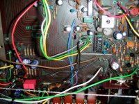
Here are some pictures:


Your comment is excellent!
I replaced power transistors with BD241C a long time ago. I used silicone pads + grease (but I would not use it again).
I have removed out the excessive amount of this grease already.
It seems like this grease dissolves aluminium heatsink and from non-conductive paste becomes conductive paste.
I replaced the voltage regulator near the filter caps as well.
But I will try to move up the signal wires feeding the power amp from the tone controls.
2 days ago I made a nice cover for the transformer and it helped a lot.
50 cm away, I can hear just some distant buzz.
70cm from the speakers I can´t hear any buzz.
The issue is EMF because Pioneer did not include a transformer cover in this model.
So the channel under this transformer is getting more EMF than the other channel.
It is grounded just on the bottom side, bcz I don´t want to make any short circuit inside the transformer with the shield.
Here are some pictures:
Last edited:
I haven't seen a Pioneer with an uncovered transformer like that. I have repaired several SX-450s over the years and those low end models had covers. I'm not sure if any USA models didn't have covers. I'm restoring an SX-550 at the moment and it had a very small amout of magnetic related hum before I bypassed some of the PCB traces with wires direct to the filter capacitors. The circuit traces were no doubt causing both induction and common current problems. The bypass surgery drastically reduced the problem and even lowered the distortion.
So, that´s interesting!
Bypass the traces around the filter caps?
I will ask you tomorrow, if I could.
I will do some pictures as well.
It is 0:30 am now.
Good night🙂
J.
Bypass the traces around the filter caps?
I will ask you tomorrow, if I could.
I will do some pictures as well.
It is 0:30 am now.
Good night🙂
J.
The 120 Hz ripple current in the trace could have been inductively coupling into a nearby input circuit. Or it may have been an undesirable mV voltage drop in the ground side “adding” to the audio signal. Either is bad design, but these things were designed long before Self’s book which explains it all clearly was written.
Thank you everyone for your replies.
So it means that I should wire every ground connection to one point?
In the first picture is marked (yellow) the grounding point for the PHONO preamp.
To this point I should route all the grounds in the amp?
But what about bypassing the traces around the filter caps?
Could someone draw it in the picture, please?
Plus and minus of the filter caps is marked (red) in the picture as well.
Thank you.
The next thing is a bit higher hissing sound.
I realized that it is caused by the tantalum caps close to the transformer. (C201,202,219,220).
The value should be 0,47uF.
I tried to put there (just out of curiosity) 0,047uF and the hiss is getting worse.So I put there 0,47uf again.
Do you think I can use 1uF tantalum caps or bypass it with some low value polystyrene caps? Would it help?
But what about the frequncy response then (or some circuit instability)? Would it get affected? (Less treble or something like that).
You do need to be very carefull with these amplifiers as they are living on the edge and go unstable pretty easy. Much of this relates to the comment from wg_ski regarding when these were designed and their limited knowledge and budget constraints at the time. I have found that white noise out of nowhere is very often instability.
I will dig up my records from my last SX-450 repair and see what traces I modified. I know that they were related to the grounding point of the high power supply filters. It did not involve any radical start point wiring. It's a matter of having a carefull look at the PCB layout with common current paths and induction etc. in mind. Pioneer made several errors but correcting the worst of them is usually enough.
The SX-550 has the filter capacitors floating on a mounting bracket and the trick there is to remove the bleeder resistors on the board and mount them on the capactor terminals and then run heavy wires back to one of the already availible holes that bypasses the offending circuit traces. The two 550s that I have done this to both experinced the same improvement in noise and half wave distortion in the power amplifiers.
Another thing to note about the SX-450 and 550 is that the power switches get oxidized and start to arc in a very radical way eventually. The switch can be carefully disassembled and cleaned and lubricated for another couple of decades of reliable use. In one case of this I found the surpression capacitor to be damaged but most of the time it was only the switch.
Thank you, if you don´t mind helping me a bit....
I don´t expect any miracles from this amp.
Just want to have it as good as it can be🙂
If I could lower the hiss and eliminate this slight buzz I would be very happy.
I compared the sound of the SX-535 and SX-450 but still don´t know which one sounds better.
But after replacing all the capacitors and four transistors in the SX-535, I believe this amplifier is much quieter and sounds a bit better than the SX-450.
And...the next thing...It is like some neverending story.
The switch AM/FM/PHONO/AUX : When the audio intput is set to PHONO and music is playing from a CD through AUX,
I can hear very little sound in just one channel (from this "bad" channel).
The switch AM/FM/PHONO/AUX : When the audio intput is set to PHONO and music is playing from a CD through AUX,
I can hear very little sound in just one channel (from this "bad" channel).
What exactly is your problem?When the audio intput is set to PHONO and music is playing from a CD through AUX,
I can hear very little sound
When input is set to phono then aux should be disconnected (ok, leave aside channel/input separation)
Hi madis64.
When I switch to PHONO with no TT connected, I can hear some music from the CD player, which is connected to AUX (in one channel),
when I turn volume control a bit more up.
When I switch to PHONO with no TT connected, I can hear some music from the CD player, which is connected to AUX (in one channel),
when I turn volume control a bit more up.
Low source separation (crosstalk between board tracks) this probably is, nothing much to do about it besides turning off other sources than the one you are listening to.When I switch to PHONO with no TT connected, I can hear some music from the CD player,
You can try shorting the unused input RCA input sockets (using shorted RCA plugs) if any such existing.
If these tracks run on the board between the used ones then the separation may "improve".
If these tracks run on the board between the used ones then the separation may "improve".
So I cleaned the switch thoroughly , shorted the unused RCA input (PHONO) and this crosstalk is gone !
It had some positive impact on the sound as well.
Thank you again for your help.
J.
It had some positive impact on the sound as well.
Thank you again for your help.
J.
These old stereos to suffer from a few less than perfect design details and indeed keeping low impedance sources connected or shorts where unused inputs exist goes a long way. Some of the impdeances involved internally also lead to all sorts of crosstalk an line hum/buzz. The SX-450 is the simplest low end model of the bunch and being the worst case makes it a great one to wring out for the experience. It's also a great one for testing mods and modules that can upgrade them to another level. I have one set aside that I hope to work on soon.
The SX-535 has an emitter follower power amp that's almost identical to the SX-550 and given that it has a bias adjustment unlike the SX-450's quasi amp, it's possible that there could be a difference. I have however had them both measure below audible distortion when properly set up. I have even tried to hear the crossover using sine waves and it takes some pretty serious bias error to make it obvious. The old Pioneers are living on the edge in many ways but it's surprising how well they can work when it's all under control.
The SX-535 has an emitter follower power amp that's almost identical to the SX-550 and given that it has a bias adjustment unlike the SX-450's quasi amp, it's possible that there could be a difference. I have however had them both measure below audible distortion when properly set up. I have even tried to hear the crossover using sine waves and it takes some pretty serious bias error to make it obvious. The old Pioneers are living on the edge in many ways but it's surprising how well they can work when it's all under control.

- Home
- Amplifiers
- Solid State
- Pioneer SX450 BUZZ