I was wondering how the Pro's here do size and specify the output inductor on a power amp. Bob Cordell suggest a range of 0.5 - 5uH and D. Self finds 2.3uH adequate for most designs. That's ok but neither one specifies a frequency at which this shall be true. So I wonder what most designers would go by.
100kHz, 250kHz, 500kHz, 1MHz ? 😕
Also what testing should be done to be convinced that the amp is stable with 'all' loads ? 😕
Square wave and loading with capacitance ? How much capacitance loading is enough to satisfy and be sure the amp is stable with 'all' loads ? 😕
This is so confusing to me 😀
100kHz, 250kHz, 500kHz, 1MHz ? 😕
Also what testing should be done to be convinced that the amp is stable with 'all' loads ? 😕
Square wave and loading with capacitance ? How much capacitance loading is enough to satisfy and be sure the amp is stable with 'all' loads ? 😕
This is so confusing to me 😀
> a frequency at which this shall be true.
This will be "air core". The effect of frequency should be near-zero until stray capacitance sets in.
> so confusing to me
We always wound a dozen turns around a 10 Ohm 2 Watt carbon-composition resistor, and it was always good.
I think the idea is to be "small" up to 20KHz-50KHz, but "large" up around 1MHz where the output devices are falling off.
I was wondering how the Pro's here do size and specify the output inductor on a power amp. Bob Cordell suggest a range of 0.5 - 5uH and D. Self finds 2.3uH adequate for most designs. That's ok but neither one specifies a frequency at which this shall be true. So I wonder what most designers would go by.
100kHz, 250kHz, 500kHz, 1MHz ? 😕
Measuring inductance with a typical meter would be done at 1kHz, perhaps up to 10kHz on more capable meters. Then there are meters which can measure at 100kHz, these are considerably more expensive. Measurement above that is certainly possible but we're starting to get out of the realms of kit accessible to the average DIYer.
As PRR states, the inductance is going to be fairly stable with frequency because its air-cored, at least until proximity/skin effect kicks in, and this only negates the internal inductance.
Save
If you are seriously trying to design an amplifier, you will find virtually everything possible with linear output stages and coils has already been done and detailed many times over. Suitable values and test results for the common output filter are well established. They are not critical values but vary with designer preferences, size and cost constraints. However, you will need to confirm the stability with real speakers and test instruments with each different design and speaker combination or dummy load - using at least test tones and an oscilloscope to observe whether there is any remaining waveform distortion. Be aware that square wave load testing with a dummy capacitive load at appropriate power levels (say, even 10W) is not necessarily simple or without risks.
To start from scratch with no prior knowledge of how it worked, it would be done iteratively, by test and measurement. That's how all commercial products are still assessed and other references may suggest. You simply need enough inductance in the heavily damped LC filter to prevent ringing - the temporary instability provoked in an amplifier by interaction between the speaker reactance and the output signal.
Bob Cordell, Douglas Self and many other authors have already said enough to meet our needs but when referring to "all loads" it covers whatever you may, even unwisely, try to drive, like an impossible one ohm speaker, highly capacitive crossover or some other daft DIY concoction. This consideration should not be necessary with normal domestic speakers but the point needs to be made because obviously, it's the speaker load that determines the amount of damping required for stability, not so much the amplifier. Too much inductance and bandwidth begins to suffer so inductances above 10uH are not a good idea yet below 0.5uH, the filter becomes ineffective with some speakers still out there. 1-3 uH is a happy medium that works for a range applications for me at least.
Normal 8-4 ohm domestic speakers will be well covered by the normal suggested values of R+L and practically, you shouldn't need to sweat this at all. A PA or musical instrument amplifier may receive a lot harsher treatment and need a little more consideration before making assumptions though.
Get some enamelled copper wire. 1mm diam to 3mm diam.
Get an AA battery.
Wind 7Turns to 15Turns around the battery. Remove the old battery. You now have a nice air cored inductor suitable for just about any Power Amplifier.
I use 7¾T of 2mm wire for amplifiers from 50W to 170W
Get an AA battery.
Wind 7Turns to 15Turns around the battery. Remove the old battery. You now have a nice air cored inductor suitable for just about any Power Amplifier.
I use 7¾T of 2mm wire for amplifiers from 50W to 170W
Get some enamelled copper wire. 1mm diam to 3mm diam.
Get an AA battery.
Wind 7Turns to 15Turns around the battery. Remove the old battery. You now have a nice air cored inductor suitable for just about any Power Amplifier.
I use 7¾T of 2mm wire for amplifiers from 50W to 170W
Yes, yes. Winding the wire around a round object works very well.
This is how I did it. 🙂

It was a fellow enthusiast that at made me think about this a little more. He was concerned that I may not have enough inductance on my Tribute Amp I posted in the SS Picture Thread. I did not want to start discussing this in the Picture Thread, so I created this Thread here.
The output coil I have calculates to be about 1.8uH with the dimensions and number of turns at 500kHz. I went ahead and managed to actually measure it on a QuadTech 7600. Depending on the measurement frequency the instrument is set to, I get a different readings.
I measure:
@20kHz, 1.2uH, Z=0.16 Ohm
@50kHz, 1.2uH, Z=0.38 Ohm
@100kHz, 1.2uH, Z=0.7 Ohm
@250kHz, 1.2uH, Z=1.8 Ohm
@500kHz, 2.3uH, Z=3.2 Ohm
@ 1MHz, 3.8uH, Z=9.6 Ohm
I would think it makes sense to spec. the coil inductance at a high frequency, a frequency well outside the audible spectrum and in a range that one would observe or expect an oscillation to occur. Does this make sense ? At this point I have not yet found a reference in the books, I may have missed it tho.
So far I am getting about 0.4 - 0.5 us group delay / rise time out of it.
I am not sure, if this is a true statement, but would this imply the amp could at most oscillate at about 1 MHz ?
I know it is controversial to wind the coil around the resistor as at this point the coils is not exactly an air coil anymore. But I believe at the frequencies we are concerned with it may not matter much. Most resistors have a ceramic body, which may not disturb much. I understand this practice is been used a lot with satisfactory results. Sure there are arguments not to do this. But that shall be discussion for another threat perhaps.
Thanks again for all the comments.
🙂
> the amp could at most oscillate at about 1 MHz ?
If the amp wants to oscillate, it *will*.
Some loads encourage it.
The coil and the Capacitor across the output, with their resistors, form a CrossOver.
Within the audio band, the amplifier "sees" the speaker, as it must.
Beyond the audio band, the crossover makes the amplifier "see" the resistors, conventionally 10 Ohms each, which limits the effective load to 5 Ohms to 10 Ohms and nearly all Resistance. It can't fall to zero (capacitor speakers) or rise to infinity (wound speakers, but will BE a reasonable size and reasonably pure Resistance.
(If there are newer theories on optimum resistor sizes, I missed the memo.)
So the goal is to not harm the Audio (whatever you define that to be) but cross over to the Resistance(s) at some higher out-of-band point.
Don't overthink it. I like 2 Watt composition resistor: non-inductive inside and out, and the coil WILL hold its shape on the road. Unsupported (AA- or lathe-wound) coils this long bother me, but you know how unlikely physical abuse will be in your house.
I measure:
@20kHz, 1.2uH, Z=0.16 Ohm
@50kHz, 1.2uH, Z=0.38 Ohm
@100kHz, 1.2uH, Z=0.7 Ohm
@250kHz, 1.2uH, Z=1.8 Ohm
@500kHz, 2.3uH, Z=3.2 Ohm
@ 1MHz, 3.8uH, Z=9.6 Ohm
Your mesurements clearly show the influence of skin effect at frequencies above 250kHz. But, as the Zobel is, or should be at least, prior to the inductor, this doesn't matter - the Zobel C will almost short-cut AC there.
Best regards!
your lathe wound inductor is too long.Yes, yes. Winding the wire around a round object works very well.
This is how I did it. 🙂
...............
This is because the bobbin you chose is too small in diameter and that resulted in too many turns being required.
Use a bobbin that is MUCH bigger in diameter.
That will reduce the turns required.
Use a wire that is thick enough to be self supporting.
I gave some guidance in post6. I suggest you at least try that and compare to your long skinny inductor.
Last edited:

Best to use is two layer inductor, soldered perpendicular to PCB, minimizing the effect of induction currents to the other parts around. Value should be less than 1 μH, diameter greater than 1,5 mm, otherwise its influence is audible.
Attachments
Last edited:
Here is some information on the oputput inductor and why its a good idea
Output L_1
You should not need an inductor of more than 2uH - a lot of us are working with about 1 or even a bit less. The actual value required will depend upon how much gain and phase margin your amp has and the worst case capacitive load you are willing to tolerate. The worst case load proposal you will find if you hunt around in the amplifier design literature is 8 Ohms in parallel with 2uF - ESL territory.
I agree with the previous poster - your coil diameter is too small - go for c. 1-1.5"
No they don't. The measurements clearly show the effect of stray capacitance.Kay Pirinha said:Your mesurements clearly show the influence of skin effect at frequencies above 250kHz.
How does a two-layer coil differ in principle from a single-layer coil?Lazy Cat said:Best to use is two layer inductor, soldered perpendicular to PCB, minimizing the effect of induction currents to the other parts around.
the two layer will show more effect from ..... capacitance...............The measurements clearly show the effect of stray capacitance.
How does a two-layer coil differ in principle from a single-layer coil?
the usual motivation, goal for the series output L is to have useful Z at the PA feedback loop unity gain intercept frequency
which varys by design, output device limitations to the neighborhood of 1 MHz
the output L could also help with local output Q instabilities in the 10s of MHz but may be limited by SRF from builtin shunt C
toroids radiate/couple less externally, have a slight reduction in SRF due the ends physical proximity increasing shunt C
I just measured this 1.0 uH, 10% fixed inductor with my dirt cheap GM328A component tester from China (link). Regrettably, the tester incorrectly identified it as an 0.2 ohm resistor instead of a 1.0 uH inductor.
However my (more expensive: USD 103!) DE-5000 LCR meter (link) did correctly identify it as an inductor, and did display the correct value: 1.0 uH.
I also made a cheap and cheerful measurement of the inductor, using a Cheapomodo bellringer jig, oscilloscope, and a precision capacitor. Same result: 1.0 microhenries. A signal generator could be used instead of a bellringer jig, of course; but I already had Cheapomodo wired up, on the bench. Took the easy route.
Conclusion: if you've wound yourself a power amplifier output inductor, and want to measure it accurately, don't bother with the GM328A -- it just doesn't go as low as you need. Use a scope and a precision capacitor, or a proper LCR meter.
How does a two-layer coil differ in principle from a single-layer coil?
"In circuit theory, inductors are idealized as obeying the mathematical relation precisely. An "ideal inductor" has inductance, but no resistance or capacitance, and does not dissipate or radiate energy. However real inductors have side effects which cause their behavior to depart from this simple model. They have resistance (due to the resistance of the wire and energy losses in core material), and parasitic capacitance (due to the electric field between the turns of wire which are at slightly different potentials). At high frequencies the capacitance begins to affect the inductor's behavior; at some frequency, real inductors behave as resonant circuits, becoming self-resonant. Above the resonant frequency the capacitive reactance becomes the dominant part of the impedance. At higher frequencies, resistive losses in the windings increase due to skin effect and proximity effect.", says Wiki.
Two layers inductor in FO amp acts great since it occupies small space on PCB, is mechanically sturdy (dipped in varnish) and as mentioned has very little induction effect to other parts around.
One of FO M builder removed output inductor, installed jumper instead and is using 2,5 nF speaker cables (see pic) without any sign of instability.
Attachments

No they don't. The measurements clearly show the effect of stray capacitance.
With an impedance and an (virtual) inductance, both growing with frequency? I don't think that.
Best regards!
Thanks everyone for the discussion and participation, very good suggestions all together.
Thanks Bonsai for the Link. This is somewhat helpful.
Thanks PRR, no physical abuse over here, all neatly stashed in a cool housing. None touches this stuff over here than me, myself and I 😉
Thanks AndrewT, Kay Pirinha, Ian Finch, abraxalito, Lazy Cat, jcx, Mark Johnson
I have some studying and lots of reading to do on this subject. I never paid much attention to this at all, doing mostly what was suggested, wind a few turns of copper to get some inductance and be done with it. I never bothered with the scientific approach. OK simulation is good but only if I understand what I am doing. For now I am not clear on this.
Having some inductance is desirable to isolate the load from the amp at higher frequencies as Bob stated in his book. OK, I go with that, makes all sense. But perhaps as mentioned I am totally over thinking this, I am not sure yet.
To summarize:
Larger coil diameter is desirable (about 25mm diameter). (Constructing it by winding around a suitable object to get the desired form factor.)
Thick copper wire, self supporting is desirable. (I used 1.6 mm, Suggested to use up to 2.0 mm)
Double layer wound coil is desirable as well.
Values of 1uH to 2uH (3uH) generally suffice for most designs. (still unanswered question, inductance to be measured or specd @ what frequency or frequency range ?)
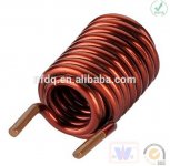
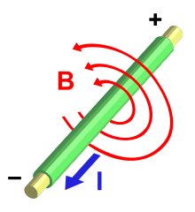
Vertical alignment of coil to minimize magnetic field interaction and coupling into signal traces suggested. (Altho I believe the field is 3D and does still couple into traces nearby, see image below)
The field is not contained in like in a ferrite core, we have an air coil, so the 'love' can potentially spread.
Thanks again for your comments.
Further comments are very welcome 🙂
Thanks Bonsai for the Link. This is somewhat helpful.
Thanks PRR, no physical abuse over here, all neatly stashed in a cool housing. None touches this stuff over here than me, myself and I 😉
Thanks AndrewT, Kay Pirinha, Ian Finch, abraxalito, Lazy Cat, jcx, Mark Johnson
I have some studying and lots of reading to do on this subject. I never paid much attention to this at all, doing mostly what was suggested, wind a few turns of copper to get some inductance and be done with it. I never bothered with the scientific approach. OK simulation is good but only if I understand what I am doing. For now I am not clear on this.
Having some inductance is desirable to isolate the load from the amp at higher frequencies as Bob stated in his book. OK, I go with that, makes all sense. But perhaps as mentioned I am totally over thinking this, I am not sure yet.
To summarize:
Larger coil diameter is desirable (about 25mm diameter). (Constructing it by winding around a suitable object to get the desired form factor.)
Thick copper wire, self supporting is desirable. (I used 1.6 mm, Suggested to use up to 2.0 mm)
Double layer wound coil is desirable as well.
Values of 1uH to 2uH (3uH) generally suffice for most designs. (still unanswered question, inductance to be measured or specd @ what frequency or frequency range ?)
Vertical alignment of coil to minimize magnetic field interaction and coupling into signal traces suggested. (Altho I believe the field is 3D and does still couple into traces nearby, see image below)
The field is not contained in like in a ferrite core, we have an air coil, so the 'love' can potentially spread.
Thanks again for your comments.
Further comments are very welcome 🙂
> Larger coil diameter is desirable
Better concept: a coil should be roughly "square" from the side. Length and diameter about the same.
(For VERY critical work (radio tuning) there may be a better L/D slightly off from 1. We are not that fussy.)
Your lathe-winding looks like 3.5:1 aspect ratio.
Taking "1" as a target, "1" could be 1mmX1mm or 1mX1m. Smaller is lower C, but that is probably not critical for the reasons given. So design a 1mm coil. For just 10 turns you must use 0.1mm wire. In my book this is #38 which is guitar pickup wire and will NOT handle speaker currents. It might carry 1.5A, but I'm not sure of that; and it is clearly awful skinny.
(Note though that your Voice Coil(s) may not be a whole lot bigger than #38, especially the tweeter. Woofs may be #26?)
Because we do not have a real space problem (like a speaker magnet gap), we would probably go #16 or so, 1.3mm diameter. 10 turns of that must be 13mm, a half-inch. As the L/D is not real critical, and a resistor is needed, and 2W resistors are cheap, 1" length on 0.3" diameter 2W resistor was a fine design.
Carbon Composition resistors are out of style. And many power resistors are getting stupidly teeny. We know that carbon on ceramic body is non-inductive but metal end-caps may be steel which changes inductance and could "saturate" in extreme cases. In radio, coils are wound on paper cardboard plastic or wood forms. In tight-tuned radio the organic materials drift from dry arctic to humid tropics but part-% drift spoils a radio and many-% drift would not hurt a load isolator. I live with trees and would not sneer at a peeled branch as a coil-form. (Dead-dry, so it does not shrink away from the winding and let it flop.) But there are many plastic bits in the more typical electronics shop. Pen casings, stand-offs, even the trimmings from skinning jumper-cable for speaker wire.
The double-back winding may have different capacitance or skin effect. I do not know but doubt it matters. Special properties are more self-supporting (when dipped to bond both layers) and both ends come out the same side (for direct PCB insertion).
> so the 'love' can potentially spread.
There are unintended consequences everywhere. I can't see how a 10-turn coil can induce big trouble in a clean transistor amp layout. However I did have a huge parasitic in a tube amp, which I believed was due to a wire-wound resistor catching field from an adjacent output transformer lead. The MHz squeal seemed to stop when I moved the OT lead away from the wirewound. I read it as a cathode-loaded oscillator. But that was long ago and I did not (still do not) have much real insight.
- Home
- Amplifiers
- Solid State
- Power Amplifier Output Inductor specification