Hello,
I hope you had a good Christmas.
I have cleaned up the tests I did on the two step-down modules.
I arbitrarily chose the voltage of 6.3V at 1.6A at the output which corresponds to my basic need.
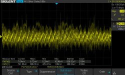
The first test is with a diode bridge. The second test with an IRM-30 15V. The 1.6A load is provided by an ETS5420 electronic load. The ripple is controlled with the scope once the module is warm.
The values of Cin and Cout were calculated by successive adding caps until the best ripple values.
The IRM module and diode bridge remain warm (around 35°C).
I have not yet done the XL6009s. This is the second time that Aliexpress has lost my package.
I ordered some PCBs of the AC version.
Regards,
Stef.
I hope you had a good Christmas.
I have cleaned up the tests I did on the two step-down modules.
I arbitrarily chose the voltage of 6.3V at 1.6A at the output which corresponds to my basic need.
The first test is with a diode bridge. The second test with an IRM-30 15V. The 1.6A load is provided by an ETS5420 electronic load. The ripple is controlled with the scope once the module is warm.
The values of Cin and Cout were calculated by successive adding caps until the best ripple values.
The IRM module and diode bridge remain warm (around 35°C).
I have not yet done the XL6009s. This is the second time that Aliexpress has lost my package.
I ordered some PCBs of the AC version.
Regards,
Stef.
Attachments


Hello,
I reworked the concept of the two PCBs between 2 Christmas meals.
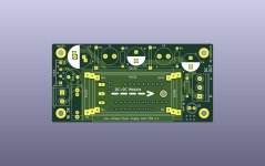
I think it will be better to make a PCB for the DC-DC module + filtering and a second PCB just for the AC-DC modules. The two boards can be mounted one below the other. I didn't like the first project because it took up too much space and wasn't versatile enough.
The AC-DC board will support 4 or 5 different module footprints (Meanwell and Hi-Link brands) up to 40W.
We can either use the DC-DC PCB alone with a diode bridge or coupled with the AC-DC PCB without the diode bridge.
The space cube used will be 110 x 44 x 75 mm for the set of two boards which remains very compact and easy to insert into a chassis vertically or horizontally.
Regards,
Stef.
I reworked the concept of the two PCBs between 2 Christmas meals.
I think it will be better to make a PCB for the DC-DC module + filtering and a second PCB just for the AC-DC modules. The two boards can be mounted one below the other. I didn't like the first project because it took up too much space and wasn't versatile enough.
The AC-DC board will support 4 or 5 different module footprints (Meanwell and Hi-Link brands) up to 40W.
We can either use the DC-DC PCB alone with a diode bridge or coupled with the AC-DC PCB without the diode bridge.
The space cube used will be 110 x 44 x 75 mm for the set of two boards which remains very compact and easy to insert into a chassis vertically or horizontally.
Regards,
Stef.
Attachments


Last edited:
Hello,
Some news about the project.
I did some tests with the DC-DC XL6009 and XL6019 step-up modules.
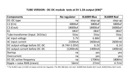
To push the tests very far, I took one of my tube amps that works with 300B under 5V 1.2A.
The power supply is very simple with a "5Vac transformer + diode bridge + 6800uF + 0R47 5W + 18000uF". It provides an unregulated voltage around 5V but drops too low if the mains voltage drops below 232V (average here 244V).
I inserted the XL6009 module between the first capacitor after the diode bridge and the power resistor.
So I now have "5Vac transformer + diode bridge + 6800uF + module + 0R47 + 18000uF". I connected the electronic load instead of the 300B tube. I simulate 1.2A under 5V.
I tested 4 modules based on XL6009. I preset the modules outputs to 5V.
The result in the table.
The "XL6009 Red step down/up module (caps 220/220uF, more HF filtering, 2 big inductors)" module provides 5V output without load but collapses at 2.8V and starts whistling as soon as I activate the load.
I started manufacturing some PCBs for the AC-DC modules. I updated the PCB images in the first post of the topic.
Regards,
Stef.
Some news about the project.
I did some tests with the DC-DC XL6009 and XL6019 step-up modules.
To push the tests very far, I took one of my tube amps that works with 300B under 5V 1.2A.
The power supply is very simple with a "5Vac transformer + diode bridge + 6800uF + 0R47 5W + 18000uF". It provides an unregulated voltage around 5V but drops too low if the mains voltage drops below 232V (average here 244V).
I inserted the XL6009 module between the first capacitor after the diode bridge and the power resistor.
So I now have "5Vac transformer + diode bridge + 6800uF + module + 0R47 + 18000uF". I connected the electronic load instead of the 300B tube. I simulate 1.2A under 5V.
I tested 4 modules based on XL6009. I preset the modules outputs to 5V.
- XL6009 basic Blue model (caps 100/220uF)
- [BEST] XL6009 Red module (caps 220/220uF + more HF filtering)
- [NOT GOOD] XL6009 Red step down/up module (caps 220/220uF, more HF filtering, 2 big inductors)
- [NOT GOOD] XL6019 Blue
The result in the table.
The "XL6009 Red step down/up module (caps 220/220uF, more HF filtering, 2 big inductors)" module provides 5V output without load but collapses at 2.8V and starts whistling as soon as I activate the load.
I started manufacturing some PCBs for the AC-DC modules. I updated the PCB images in the first post of the topic.
Regards,
Stef.
Attachments
Last edited:
Hello,
I uploaded a LVPS Mini PCB canvas in KiCad 6.x format for those who would like to make a PCB that fits on the AC-DC LVPS-PCB.
The file is available on my Github repository.
https://github.com/stefaweb/audio-psu/tree/main/LVPS-PCB-MINI/LVPS-PCB-MINI-BASE-KICAD-1.0
Regards,
Stef.
I uploaded a LVPS Mini PCB canvas in KiCad 6.x format for those who would like to make a PCB that fits on the AC-DC LVPS-PCB.
The file is available on my Github repository.
https://github.com/stefaweb/audio-psu/tree/main/LVPS-PCB-MINI/LVPS-PCB-MINI-BASE-KICAD-1.0
Regards,
Stef.
Attachments

Hello,
I received one of the prototype PCB. It works perfectly.
The various DC-DC modules fit into the footprints without any problem.
I'm not very rich in 10V capacitors. I found two Rubycon ZLH of 4700uF (C2) and 2200uF (C3) for testing.
For the measurements, I am a little better than during the flying wiring tests.
So far I've only tested the XL4015. With a 12Vac transformer at the input and 6.3Vdc 1.6A at the output, I get a ripple of 2.6mV rms (10mV pk-pk).
I am now waiting for the AC-DC module PCB.
Regards,
Stef.
Attachments

Last edited:


This migh help somehow?
For those who looking for something like this
- savan
- Replies: 4
- Forum: Power Supplies


Hello,
Gerber files are available on my Github repository.
I still have to do various tests to maybe find a better inductor for the LVPS-PCB-MINI. I have the impression that the one I use saturates above 1A. You can also simply use a 0R1 2W resistor. The results are a little less good but it is marginal.
Regards,
Stef.

Hello,
I have redone comparative tests with the LVPS-PCB-MINI in AC version. It is still much better with an inductor than with a resistor for the CRC/CLC output filter.
With an AC 12V input and the HW-468 regulator on 6.3V 1.6A, we have a big difference.
Ripple with 0R1 2W resistor: 2.95mV (12mV pk-pk)
Ripple with 10mH 2A inductor: 660uV (5.6mV pk-pk)
The 10mH 2A inductor I bought on Aliexpress some time ago is no longer available in the store. I found another one almost identical. The ferrite powder ring seems a little bigger (20mm instead of 16mm). The wire is the same size: 0.6mm.
https://fr.aliexpress.com/item/1005006533183666.html
If anyone has tried different inductors, I would be interested in hearing about their experience.
Stef.
Attachments

Last edited:
hey glad i have found this thread. I am also building a buck based on XL4015. Not really audio related, the intention is to power a raspberry pi 5 and other stuff from a USB PD charger (15V -> 5V).
I kind of regret going for the XL4015 as nowadays there are other options that don't require big inductors and electrolitic caps, but well, too late for this time, PCBs are already done.
I got the XL4015 chips also from aliexpress modules but what i got are definitely not original XLSEMI chips (they have no "XLSEMI" marking and no pin 1 mark, and they all switch at 200kHz), but seem to work well.
My schematic is basically the recommended circuit from the datasheet, i just added a small ceramic capacitor at the output to eliminate the high frequency noise from the switching edges that i was seeing at ca. 50MHz (worked great), and now i am experimenting with the output cap. I see that what has more influence on the ripple is the ESR, and i get my best results with a 100uF panasonic FK series cap that i had laying around. But it is only 100uF and i am afraid it wont be enough for the current demands of the raspberry pi (no clue). I want to try something with a higher capacitance and even lower ESR, the best i can find that fits my 8mm diameter footprint is panasonic EEEFT1V331GP. I dont have the space/footprints necessary to put additional parts. Any thoughts?
I am going to answer myself. Added a solid polymer cap that I got from a usb charger I took apart, with ESR 10mOhm and 4.3Arms rated ripple current and the ripple voltage is now so low I cannot detect it with my cheapo scope.

Hello,
I don't have much time to look at this but I will do some tests. I have some polymer capacities in stock.
Stef.
I don't have much time to look at this but I will do some tests. I have some polymer capacities in stock.
Stef.
Hello,
I made a new version of the LVPS-PCB-MINI module PCB for XL regulators and others.
I managed to fit a two-stage filter on the PCB. It takes less space than the old filter and gives the first measurements a 3mV ripple at 6.3V 1.5A output.
I also added 2 resistor footprints under the PCB to create an optional midpoint for use with audio tubes.
I should put the files online this weekend.
Regards,
Stef.
Attachments


Looks great. So have solid polymer caps been an improvement? Do you mind sharing the reference for the ones you used? Thanks!
Yes polymer capacitors are better in this case and they take up much less space. With the new filter, there is also no need for C2 when using with an AC-DC power supply. C2 is needed if you use the PCB with a diode bridge.
Small 0R040 metal resistors are not easy to find. At the moment only Digikey has them in stock.
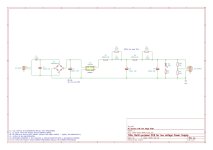
The parts references are on the full diagram and there will also be a BOM.
Stef.
Small 0R040 metal resistors are not easy to find. At the moment only Digikey has them in stock.
The parts references are on the full diagram and there will also be a BOM.
Stef.
Attachments

Hello,
I have uploaded a new version of the PCB for the AC-DC modules now.
Version [1.0.2] (23-03-2025)
Gerber files can be downloaded from my Github repository.
Regards,
Stef.
I have uploaded a new version of the PCB for the AC-DC modules now.
Version [1.0.2] (23-03-2025)
- Added support for Faston connector for output terminal socket.
- Enlargement of RV1 holes.
Gerber files can be downloaded from my Github repository.
Regards,
Stef.
Attachments

Last edited:
- Home
- Amplifiers
- Power Supplies
- Power Supply PCB for DC-DC modules as XL4015, XL6009 and others