Thank you
I wasn't sure how to check, found a post on how to do that using DVM.
Transformer has six wires marked
Yellow(0V)-Blue(28V)-White(36V) 500VA
Yellow(0V)-Blue(28V)-White(36V) 500VA
I have checked by connecting two 0V wires ad measuring voltage across two free ends 36V wires , DVM shows 0V AC.
Method to find phasing asks to swap one secondary wire in case recorded voltage is 0V AC
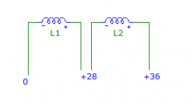
36V AC(free end) 0V AC(same secondary) joins to 36V AC(other secondary) 0V AC(other free end).
Is that what you want me to check?
Now I understand 😀, that is exactly what is in the sketch.
Primary is
0-110V
0-110V
Currently I have them connected for a 240V mains.
Last edited:
It's really weird that the two secondaries would be wired in phase instead of the normal out of phase to get +/- supplies... but the multimeter doesn't lie...
......
I have checked by connecting two 0V wires ad measuring voltage across two free ends 36V wires , DVM shows 0V AC.........
that's enough
you have some weird xformer there, no possibility to have symmetrical 28Vac taps
you can have just 36-0-36
Thank you
Sharing some measurements
0-110
0-110
Currently primary tested in 240V configuration, finally will be used in 120V configuration.
Sec1 Yellow(0V)-Blue(28V)-White(36V) 500VA
Sec2 Yellow(0V)-Blue(28V)-White(36V) 500VA
If I connect 0V(Yellow Sec1)-0V(Yellow Sec2), other two free ends(blue Sec1-blue Sec2 and white Sec1-white Sec) measure 0V.
If I connect White Sec1 and Yellow Sec2
Voltage between Yellow Sec1 and White Sec2 is 72V
Also do you see any problem with attached image, if I use 4 bridge rectifier to create +/-28V and +/-36V DC
Attachments
Last edited:
That is unfortunate, it is obviously not designed to be used symmetrically (positive and negative) as you need...
You can do 36-0-36 volts as you have with White to Yellow
or 28-0-28 if you join sc1 Blue to sec2 Yellow and use the other Yellow and Blue for the output. (Leave the Whites disconnected.)
You can do 36-0-36 volts as you have with White to Yellow
or 28-0-28 if you join sc1 Blue to sec2 Yellow and use the other Yellow and Blue for the output. (Leave the Whites disconnected.)
Also do you see any problem with attached image, if I use 4 bridge rectifier to create +/-28V and +/-36V DC
This transformer can't make +/-28V and +/-36V DC at the same time with full wave rectification. With half wave rectification it can, but voltage ripple will be a lot higher.
If it is a toroid, maybe you can modify the winding on the outside. You'd have to change the position where the 28V tap is connected.
If it is an EI core, maybe you can modify the way the windings are connected to the terminal block.
Can you post a pic?
Thank you
Its a Toroid
---------------------------------------------------------------------
0-110
0-110
Currently primary tested in 240V configuration, finally will be used in 120V configuration.
Sec1 Yellow(0V)-Blue(28V)-White(36V) 500VA
Sec2 Yellow(0V)-Blue(28V)-White(36V) 500VA
--------------------------------------------------------------------
I checked with continuity tester
0-110(First pair)
0-110(Second pair)
They can be connected in series or parallel for 240V or 110V.
0-28-36(First pair)
0-28-36(Second pair)
There is no continuity between pairs.
Attachments
Last edited:
It should be wired like this:

That's a 28V winding and a 8V winding in series.
Or it could have a 28V winding and a 36V winding joined at the "0V" output, but that would be a bit unusual.
Can you feel if there are two wires from the windings inside one of the heat shrink tubes?
If this is the case, and you can separate these wires and get individual windings instead of series connected with a tap, then that would solve your problem.
Yes indeed. The picture shows that the individual secondaries can be accessed separately. So it is a matter of reversing one secondary and Bob's your uncle.
Jan
Jan
Thank you
Under the heat shrink, its just one wire.
I am thinking of opening up one of the transformer. Will get back.
Under the heat shrink, its just one wire.
I am thinking of opening up one of the transformer. Will get back.
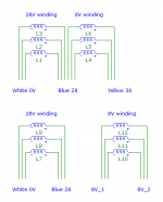
Please see attached images(Image name is wire color)), all secondary have three wires coming in except blue which is connected to 5 wires.
Let me know what else to check.
Also does it matter whether primary 0-110,0-110 are connected in series or parallel?
Currently its in series for 240V
Let me know what else to check.
Also does it matter whether primary 0-110,0-110 are connected in series or parallel?
Currently its in series for 240V
Attachments
Last edited:
Are you sure there are only 5 wires on the Blue connection? It needs to be 6.
If you are brave you can split the wires on the Blue connection. 3 will go to the White wire and the other 3 will go to the Yellow wire.
Solder the 3 that come from the Yellow end back to the Blue wire.
Now solder another coloured wire to the 3 you have split and make another lead out.
That gives you 4 wires out like peufeu's picture in post #29.
Yellow to Blue should give 28 volts and the new lead to White should give you 8 volts.
There has to be no connection between the Blue and new coloured wire, make sure!
That's good.
You need to do the same to both secondaries of course.
You will end up with 8 lead out wires and 4 secondaries.
Now you do need 4 bridge rectifiers and 'stack' them positive to negative like the picture.
Remember the DC volts at the caps will be a lot more than the AC volts in. (1.41 times)
Alan
You need to do the same to both secondaries of course.
You will end up with 8 lead out wires and 4 secondaries.
Now you do need 4 bridge rectifiers and 'stack' them positive to negative like the picture.
Remember the DC volts at the caps will be a lot more than the AC volts in. (1.41 times)
Alan
Attachments
Last edited:
Thanks you
If you are brave you can split the wires on the Blue connection.
- I can make change but I do not understand the existing wiring.
3 will go to the White wire and the other 3 will go to the Yellow wire.
-There are six wires connected to blue(two groups of 3 wires), which group to connect to white and which to yellow.
-After this step there is nothing connected to blue, right?
-Earlier when I was testing the Transformer, blue accidentally touched white wire and created a spark, wont this step create a problem?
Solder the 3 that come from the Yellow end back to the Blue wire.
-Not clear "the 3 that come from the Yellow end". There are only three wires going in and connected to yellow.
Now solder another color wire to the 3 you have split and make another lead out.
-Not clear, which ones?
3 go to yellow and 3 to white, there is nothing left.
That gives you 4 wires out like peufeu's picture in post #29.
Yellow to Blue should give 28 volts and the new lead to White should give you 8 volts.
- This I understand, but I don't understand existing wiring of my transformer so not able to make out last 2 steps.
There has to be no connection between the Blue and new coloured wire, make sure!
Last edited:
Easy,
Split the 6 enamelled wires from the Blue lead out wire.
With your meter on 200 Ohms range, put one clip on the Yellow lead out wire.
Now touch the other meter probe to the free ends of the enamelled wire, 3 will give you a low resistance reading, 3 will give you an open circuit.
Join the 3 low resistance wires together and solder them back to the original Blue lead out wire. That is the 28 volt winding, Yellow to Blue.
Now join the other 3 enamelled wires together and add a new lead out wire. Insulate it carefully from the other lead outs. That New Coloured lead to the White lead is your 8 volt secondary.
Does that make sense?
Absolutely, now I understand. Let me draw and share again to make sure I am not making any mistake.
It looks like the wiring corresponds to the illustration on top.

If you split the 6 wires into 2 groups of 3 you get two independent windings (28V and 8V) that you can then rearrange as you like.
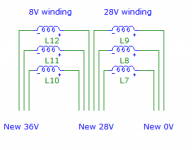
For example you can do this:

So you can move the 8V winding to the left, and relabel the wires as shown on the schematic, while inverting the polarity. And that will give you 28V and 36V with the opposite AC polarity of the other 28/36 winding.
Then you can use the circuit with the 2 bridge rectifiers and it will work.

If you split the 6 wires into 2 groups of 3 you get two independent windings (28V and 8V) that you can then rearrange as you like.
For example you can do this:

So you can move the 8V winding to the left, and relabel the wires as shown on the schematic, while inverting the polarity. And that will give you 28V and 36V with the opposite AC polarity of the other 28/36 winding.
Then you can use the circuit with the 2 bridge rectifiers and it will work.
- Home
- Amplifiers
- Pass Labs
- Powering two PSU from one Transformer


