Or drop that idea and start looking for 6P42S/6P45S ...😕
I did split the mains transformer to have the amp operating as a quasi monoblock, so I have actually 2 by 225V PSUs inside. (But no bias voltage).
I did split the mains transformer to have the amp operating as a quasi monoblock, so I have actually 2 by 225V PSUs inside. (But no bias voltage).
My earlier suggestion to try Priboi with 6P45S/PL519-family tubes is based on my experiments with these tubes
with almost similar load impedance and supply voltage.
Actually the OPT of Priboi should be very suitable for these sweep tubes.
with almost similar load impedance and supply voltage.
Actually the OPT of Priboi should be very suitable for these sweep tubes.
I got about 100W from 6P45S at 1kHz with the priboj OPT.
At 30Hz still 80W which is really nice in my opinion.
I did not get rid of the problem yet.
Does one of you guys have a suggestion what i could try...?
At 30Hz still 80W which is really nice in my opinion.
I did not get rid of the problem yet.
Does one of you guys have a suggestion what i could try...?
To me is not clear if both channels have hum or not. This information would be essential.
Anyhow, try to measure (with a scope) the ripple at main +Ub but also at 6N6P and 6J32P.
You can check if the higher capacitance is required by adding (suitable voltage rating) electrolytic capacitor at parallel with the existing ones.
Anyhow, try to measure (with a scope) the ripple at main +Ub but also at 6N6P and 6J32P.
You can check if the higher capacitance is required by adding (suitable voltage rating) electrolytic capacitor at parallel with the existing ones.
Finally... The amp works again.
Someone told me to swap C5 and to solder the pads of the feedback R and C again and now the popping noise is gone away.
I don't know what solved the problem as i did both things at the same time but i am very happy now.
Someone told me to swap C5 and to solder the pads of the feedback R and C again and now the popping noise is gone away.
I don't know what solved the problem as i did both things at the same time but i am very happy now.
In Bruce Rozenblit's book, Audio Reality, he shows a simple PP-amp with a punch. Using a a pair of EL-509 in each channel he gets a smashing 150W with a Hammond 1650T transformer and a 6BM8 screen grid regulator. Vsupply = 700V.
Look at the post 5 of this thread. There is the schematic of my 6P45S PP with 2k OPT and some 460 V supply voltage . It delivers 170 W.
Living with a motto: A lazy engineer is a good engineer", I will definitely suck in everything from you, Artosalo!🙂
Btw, there should have been a UM75-version with quad 6R3S/channel. I wonder if the existing transformers were intended to be used with the bigger 75W model.
Btw, there should have been a UM75-version with quad 6R3S/channel. I wonder if the existing transformers were intended to be used with the bigger 75W model.
Btw, there should have been a UM75-version with quad 6R3S/channel. I wonder if the existing transformers were intended to be used with the bigger 75W model.
As far as I know the UM-75 is just a version with higher supply voltage but with the same tubes as UM-50.
Another Update:
I was to enthusiastic...
Swapping the cap C5 was not a success.
Soldering C11 back in place solved the problem with the popping noise.
Soldering C10 back in place increased the stability/performance of the amp.
It seems they are not there just for fun.
Maybe they are just some kind of bug fix on the priboj...
Could someone explain to me what those caps do?
It seems C11 suppresses the unwanted noise on the G1 and leads them to ground...? C10 is some kind of filter??
This will be a Summer 20XX project. Just ordered four EL504 from Conrad.se, the German company's shop in Sweden. Incloding sockets and anode connectors - $60 all four. About quality, I know nothing.
Could someone explain to me what those caps do?
It would be possible to analyze why some components placed at a bit odd places are there if the amplifier were in my hands to do some tests and measurements, but because it is not, the answering to your questions is not that easy.
The reason for C11 is unknown for me. However it forms a low-pass filter with R20, but why such LPF is only at the other output tube is strange.
C10 decreases the gain of 6J32P at high frequencies and is there to add stability, which may be critical due to GNFB.
BUT, the (new) value of C10 should be determined. I assume the amount of GNFB is 14 dB (1:5) as you told earlier. If you put the original 300 pF C10 back in place, I doubt the frequency response may be attenuated above 10 kHz. I assume that the optimum value for C10 is now less than 300 pF.
Last edited:
Today i "matched" my 6P45S tubes.
Made a simple test setup with anode voltage, G1 + G2 voltage and a socket. I adjusted the voltages and i tested all tubes with the same voltages.
Got anode current values from 30 to 60mA and a dead tube...
Now i have 2 "matched pairs" of tubes in my amp.
Tomorrow i will receive some caps with pF values. I will try to use different values for C10, C11 and the feedback cap to hopefully get a good result.
As i got popping without C10/11 i was not able to test other values for the feedback cap - i hope a bigger value will decrease the high frequencies to a normal level.
I also got a nice NAD preamp with treble and bass control from a friend to test the amp properly. 🙂
Update:
Now the amp is running stable and the sound is finally great!
Things i changed:
-> C10 is now a 220pF cap just as C11. (don´t know if this changed the sound significantly...)
-> feedback cap removed!!! This definitely improved the sound quality and was the major problem!!
-> feedback R is 6,8k Ohm again.
If anybody is interested, here is the new circuit with all changes:
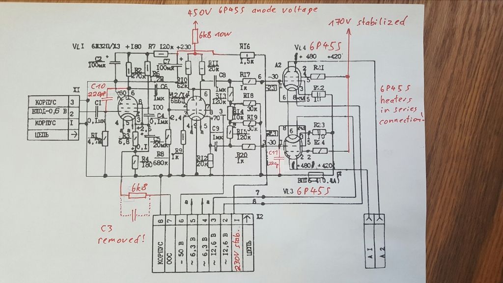
Now with these changes i would definitely recommend the mod! 😉
feedback cap removed!!! This definitely improved the sound quality and was the major problem!!
Have you done 10 kHz square wave test ? Result ?
feedback R is 6,8k Ohm again
How much is GNFB now ?
Have you done 10 kHz square wave test ? Result ?
No. But i can do it. At which output power/voltage?
How much is GNFB now ?
6,8k is the original value...
Like i said if you increase the value you get hum.
The square wave test can/should be done at different power levels, but you can see the possible rining etc. best at some half of the max. output voltage.
Take care that the signal is well below clipping level.
6,8k is not a value of GNFB, just the value of one resistor.
The amount of GNFB is the difference of the open loop gain (no-GNFB) and closed loop gain (with GNFB) in dB.
If there is hum at lower amount of GNFB, then there is still something to fix.
Now this "bug" is hided by GNFB, not fixed.
Take care that the signal is well below clipping level.
How much is GNFB now ?
6,8k is the original value...
6,8k is not a value of GNFB, just the value of one resistor.
The amount of GNFB is the difference of the open loop gain (no-GNFB) and closed loop gain (with GNFB) in dB.
If there is hum at lower amount of GNFB, then there is still something to fix.
Now this "bug" is hided by GNFB, not fixed.
6,8k is not a value of GNFB, just the value of one resistor.
Yes, i know. On the first page you said this should be about 20dB. I know that i have different tubes now but i am finally happy with the results... It was enough to carry the 18kg amp about 50 times from the main floor into the cellar and back - i hope you understand. If anybody wants to make the ultimate 6P45S priboj mod where everything is completely perfect i will not stop him but for me the amp is really good right now as it is...
Square wave test at 20V - 8Ohm (1/10 probe)
Compared to your shots of the square wave i would think this is not bad at all.


I said as follows:
The original GNFB is >20 dB which is relatively high value and sometimes Pribois have shown to suffer from stability problems. Therefore I suggested lower GNFB value than original.
However, the square wave response seems very good, actually I am even surprised.
So the OPT of Priboi is relatively good. And the compensation you have achieved seems to be at optimum.
The GNFB (negative feedback) components must be re-dimensioned. If the total GNFB is below some 15 dB the stability of the whole amplifier is obviously better.
Originally the GNFB is above 20 dB.
The original GNFB is >20 dB which is relatively high value and sometimes Pribois have shown to suffer from stability problems. Therefore I suggested lower GNFB value than original.
However, the square wave response seems very good, actually I am even surprised.
So the OPT of Priboi is relatively good. And the compensation you have achieved seems to be at optimum.
Ok alright, above 20dB.
Finally some good news. So my ears seem to be right.
Thanks for everything, artosalo.
Finally some good news. So my ears seem to be right.
Thanks for everything, artosalo.
- Status
- Not open for further replies.
- Home
- Amplifiers
- Tubes / Valves
- Priboj with other tubes