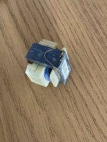
Hello, due to bad transportation I have just found out a little transformer detached from a pcb in my just acquired HK 1.5 signature.
I think the problem is easy to solve but I don’t know how to reconnect it.
Where should I solder the two tiny copper wires?
Should I glue it to avoid that it detaches again?
Here are some pictures.
Thank you so much for helping
I feel a bit miserable, the package was not well made, inspite of many recommendations :-(
Attachments


Last edited:
You will need to get a new transformer. This is un-repairable as both primary and secondary wires are broken and primary ones are very thin to be saved.
Attached may be the manual for your unit. Would you confirm? https://manualmachine.com/harmankardon/signature15/2362299-schematic/
That's an amazingly small transformer. You should be able to find a chassis mount substitute. You might use a bench supply or a 12V
wall-wart temporarily while you finish debugging.
That's an amazingly small transformer. You should be able to find a chassis mount substitute. You might use a bench supply or a 12V
wall-wart temporarily while you finish debugging.
Attachments

Thank you, this is better than the one I found!Attached may be the manual for your unit. Would you confirm? https://manualmachine.com/harmankardon/signature15/2362299-schematic/
That's an amazingly small transformer. You should be able to find a chassis mount substitute. You might use a bench supply or a 12V
wall-wart temporarily while you finish debugging.
Do you really think I will not be able to fix it? :-(
And what is the role of this transformer? Is this just for the light in the front fascia?
Last edited:
Transformer powers lighting and low voltage for relay switching.
You might be able to fix the transformer. Maybe you can connect to the leads. Maybe you can disassemble the transformer enough to remove one turn to gain some lead length. Maybe you can find a drop-in replacement! Worth a shot. And as you suggested, glue or clamp or zip-tie, etc.
I suggested the temporary fix so you can determine other problems not yet discovered.
Thank you again.
I can only see two leads coming out so I guess this will make things more difficult 😣
I can’t figure what a jump the parcel must have done to have that transformer demounted..
I can only see two leads coming out so I guess this will make things more difficult 😣
I can’t figure what a jump the parcel must have done to have that transformer demounted..
I guess it would only be more waste of time..File a claim immediately.
Unfortunately many people don’t understand the importance of the shipping and they just don’t pay enough attention to make a good parcel (even though I asked to be careful..)
If the guy had put just some padding on the bottom of the box instead of laying the amplifier directly on it he would have saved the unit (and my time).
When I picked up the parcel and heard a piece of metal moving inside the chassis I felt like crying 😭
Heavy items MUST be double boxed, with resilient packing material in between the boxes.
Consumer electronics is not designed for high impacts.
Consumer electronics is not designed for high impacts.

Thank you for your advice but I would like to try to leave it in its original state as much as possible. This amplifier was not cheap and it’s in very good shape, I would day as new, It think I am the first one to open it (this makes me even more upset).Take a cheap 15vdc wall wart and wire it in....
From your comments I understand the work is unfortunately beyond my skills so I will have to go and chase my technician, which is good, but it’s not close and it’s a pain to reach..
Let’s hope there are no other damages, and let’s hope the seller wants is responsible enough to pay for the repair
What a pity.
It is not obvious from your photos how the transformer was attached. Normally, the bobbin would have mounting pins which in your case would have all detached. Seems to me that that is a design problem with the transformer. I generally avoid PCB mounted transformers for exactly that reason. But one commercial amplifier I did a tear-down on had very sturdy pins, and two lines of them, giving a strong mount.
I don't think the chances of saving the transformer are good. You need to gain access to the broken wires and attach leads to them, suitably insulated. Often the outermost wire connections can be got hold of by unwrapping the overall insulation, but the usual difficulty is whether the innermost (the start of the winding) has broken close to the winding, making it difficult to get enough of the wire to make a connection without damaging other wires next to it and risking a short circuit. You have two coils, from the images, and you need two wires to each, one wire to the inside (start) of the winding and one to the outside (end).
One turn lost on the outside, to give you more wire to play with, is probably not an issue, but it's the inner connections which can be the limiting factor.
If you cannot see all the loose ends, this could be a problem. You may get a better view by dismantling the core, but often there is a varnish which makes this very difficult as the laminations stick together. If you manage that, then unwinding the outer insulating plastic strips is easier, but there is still no guarantee you will be able to get hold of the inner wire ends. If you do manage to do all that, then any flying leads added to reconnect the transformer need to be insulated and protected from the rest of the windings. Soldering can sometimes leave a thicker "blob" with, if not done well, some solder spikes that need to be pressed down so as not to puncture any other insulation you may apply. Tricky.
Probably best cut your losses, demand a refund possibly, and purchase a similar size replacement.


- Home
- Amplifiers
- Solid State
- Problem Harman Kardon power amplifier