Thanks for the tip, @Juhazi !
Ok, back to measuring....
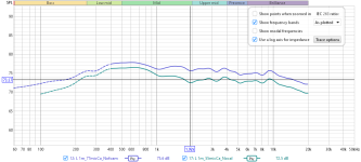
I did an 1m from the spot between the T and M to compare the 2 mics I have and...
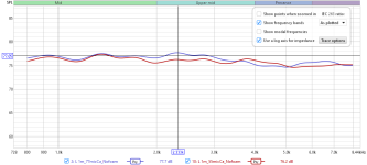
This image shows the difference but just swapping them the newer mic was -20db lower??!?!? I had to recalibrate to get it to match. Something is iup.
I've been listening to the ideal xo that I used real measurements to time align and fix some eq issues. I decided to try and modify it a bit making the mid-range have a tilt to it. The optimizer in vcad found a change to the XO.
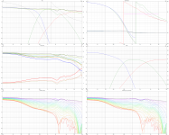
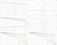
The new xo vs old with the newer mic:
The decay looks better with the only change being a tilt to the mid-range:
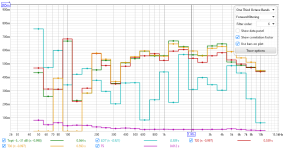
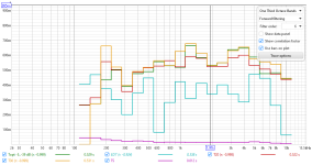
This is still between the T and M on both measurements. It is interesting how power and decay play on a baffle.
The sound of the new XO has more depth to it to my ears. Now I just need to figure out what is up with the mics and what to trust.
Ok, back to measuring....
I did an 1m from the spot between the T and M to compare the 2 mics I have and...

This image shows the difference but just swapping them the newer mic was -20db lower??!?!? I had to recalibrate to get it to match. Something is iup.
I've been listening to the ideal xo that I used real measurements to time align and fix some eq issues. I decided to try and modify it a bit making the mid-range have a tilt to it. The optimizer in vcad found a change to the XO.


The new xo vs old with the newer mic:

The decay looks better with the only change being a tilt to the mid-range:


This is still between the T and M on both measurements. It is interesting how power and decay play on a baffle.
The sound of the new XO has more depth to it to my ears. Now I just need to figure out what is up with the mics and what to trust.
The RT60 (includig EDT) analysis is for measuring the room decay, not the speaker, even in (semi)nearfield. It is too coarse to analyze such relatively small changes in speaker response or directivity.
I can hardly see a difference between a 2-way and dipole multiway.
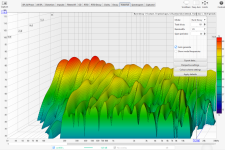
REW has better suitable views for erly decay, like Decay in CSD mode (cumulative spectral decay) or Waterfall in Burst decay mode,and the user can adjust parameters with Control toolbox. This way you can take a closer look at what happens during the first 20 ms. But directivity changes make only minor effects in them.
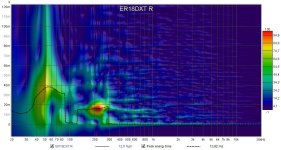
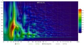
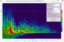
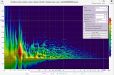
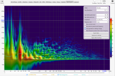
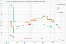
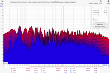
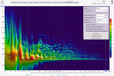
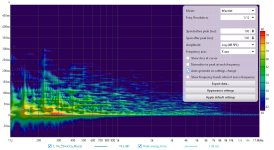
I have learned to look at Spectrogram in Wavelet mode of room response. It shows well how modes and reflections come to the mic in the room. This is the best way to "see" how different kind of speakers sound in a room, IMO.
Here same room measurement with the speaker in normal listening position, mic 2,5m from the speaker, just in front of my head. Just different analyses of same measurement:


Last edited:
Thanks. I understand. The spectrogram can be finnicky to setup and the rt60 is easy to look at. In all cases I am measuring a point in space and looking at a graph that represents it. I was just comparing two measurements at the same spot where the only difference was an xo. The point between the two drivers had the most mess and it was surprising to see it improve.The RT60 (includig EDT) analysis is for measuring the room decay, not the speaker
to quote the REW manual:
EDT-Early Decay Time, based on the slope of the Schroeder curve between 0 dB and -10 dB. This is not an RT60 figure, but rather an indication of how quickly the initial sound at the measurement position decays - it is much more location dependent than RT60. A fast early decay (low EDT figure) indicates better clarity than at positions where the EDT is higher.
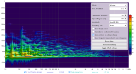
I think each graph has a use but this is not as clear as the EDT. A lower rounding like 1/6th is closer to human hearing.
Thanks for the tips, @Juhazi !
Was your ER18DXT speaker close to the wall?
ER18DXT was measured in 2013 and it was my main speaker before AINOgradients. It was about 2' from wall just like others. Furniture was same too. All room measurements are difficult to compare to others, because there are so many variables. MR183 was measured in 2018, I made them for one of my daughters. v35 of AINOgradientt was measured in spring 2024. Only v35 is dipole, ER18DXT is "normal" 2-way monopole, MR183 has coaxial MT and downfire woofer.
Greatest difference in spot decays I saw for different versions on AINOgradients (dipoles) was when I added a backside tweeter. Before that there was practically no rearsector radiation above 3kHz. Later on I moved to planar tweeters to get even smoother horizontal pattern
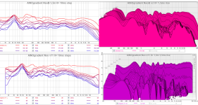
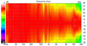
Horizontal polars (ER only to 90deg) ER18DXT is widest at 1-5kHz
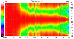
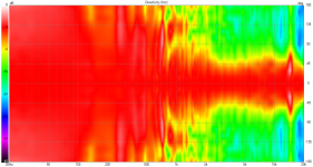
Greatest difference in spot decays I saw for different versions on AINOgradients (dipoles) was when I added a backside tweeter. Before that there was practically no rearsector radiation above 3kHz. Later on I moved to planar tweeters to get even smoother horizontal pattern

Horizontal polars (ER only to 90deg) ER18DXT is widest at 1-5kHz


Just ordered some FA253's for this project. (Anyone interested in hypex plate amps should contact sales directly (there is a sale). I assume a new plate amp is on the way but don't care)
It will be neat to mess with FIR filters.
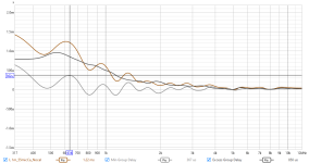
I am pretty happy with the GD of the current XO. Here is a time adjusted measurement on axis:
The JA-0801 is so nice to listen to. It has made me buy some tracks that I was previously happy with just listening to on spotify.
https://www.prestomusic.com/classical/products/7928424--saint-saens-le-carnaval-des-animaux
I love that track.
It will be neat to mess with FIR filters.
I am pretty happy with the GD of the current XO. Here is a time adjusted measurement on axis:

The JA-0801 is so nice to listen to. It has made me buy some tracks that I was previously happy with just listening to on spotify.
https://www.prestomusic.com/classical/products/7928424--saint-saens-le-carnaval-des-animaux
I love that track.
Got the new amps for this project. The hypex screen is pretty much the same size as the old IR sensor. For some reason I thought it would be larger.
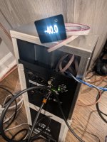
The bud industries AC-433 aluminum box (it was cheapest on amazon) holds the plate amp just fine with room for 3 neutrik connectors at the top. I'll design a laser-cut top for it later- tape and skewers for now.
This week I am going to A vs B vs C a few speakers since I now have 4 plate amps.

The bud industries AC-433 aluminum box (it was cheapest on amazon) holds the plate amp just fine with room for 3 neutrik connectors at the top. I'll design a laser-cut top for it later- tape and skewers for now.
This week I am going to A vs B vs C a few speakers since I now have 4 plate amps.
A long time since I posted here, but I haven't forgotten my JA0801 BE domes. My latest is an effort to make this driver more useful by making it easier to mount into a baffle, integrating a 3D printed waveguide for more consistent directivity. To be flush mounted, it has to mount from behind the baffle, like the Volt VM752 and ATC mid domes. I can also reuse the original wire grill to protect the precious BE dome. On this first iteration, the mounting hole needs to be 6" diameter, but it could be made smaller -- perhaps 5", which would be better. The mounting depth is 18mm, to match the minimum Baltic Birch plywood thickness I use for baffles.


It'll be a while before I can get around to smoothing the 3D print surface & mounting it in a baffle for use & testing.
It'll be a while before I can get around to smoothing the 3D print surface & mounting it in a baffle for use & testing.
I just used the standard shape of the quarter-round router bit used for previous experiments. Haven't listened much but didn't notice any difference in a quick listen -- compared to previous waveguide. This one should be better because the fit is much tighter to the dome.
There are 2 things that might be improved:
1. There's about a 1-2mm gap between the WG bottom surface and the surround. It might better to close this gap -- but still avoid touching the surround lest noise is created by vibration.
2. The diameter of the WG could be reduced to ~5" or perhaps even less. Minimizing the driver hole would be better for the rigidity of the front baffle.
- Home
- Loudspeakers
- Multi-Way
- project: Emperor L26ROY (tweeter + Yamaha JA-0801 + Seas L26ROY)
