 non-powered ?
to determine which side ( upper or lower) is responsible for oscillation , make this simple test -
take 220R with plastic tweezers and put it in parallel to one gate resistor
you can start from lower side
if osc. increases , that's most probably problematic side
btw. it can help to gnd heatsinks
take 220R with plastic tweezers and put it in parallel to one gate resistor
you can start from lower side
if osc. increases , that's most probably problematic side
btw. it can help to gnd heatsinks
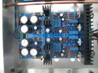
Despite my best intentions to finish the Pumpkin preamplifier last year, things got in the way of completing that project. Zen Mod's documentation is good so purchasing the parts and assembling the PCBs was a breeze. The problem was finding a suitable case that would fit the boards and allow for short signal wires. I purchased a 2U Pesante from the DIYAudio store, but it was a tight fit.
2U Pesante (Maximally Vented) - Full Width with No Heatsinks - Chassis
So I decided to build one tailored to the project.
2U Pesante (Maximally Vented) - Full Width with No Heatsinks - Chassis
So I decided to build one tailored to the project.
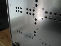
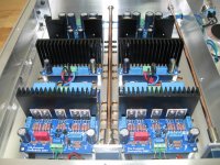
I started with a 1/8" aluminum plate purchased as remnant from a local supplier. Using the table saw with a Freud blade for non-ferrous metals I cut the bottom, sides and back panel. From a 3/16" aluminum plate, also purchased as remnant, I cut the front panel. The top uses perforated aluminum from the same supplier.
The pieces are joined with aluminum angle and #6 socket head screws. The bottom uses stainless steel #6 screws and the holes are countersunk.


The pieces are joined with aluminum angle and #6 socket head screws. The bottom uses stainless steel #6 screws and the holes are countersunk.
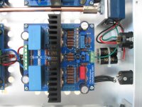
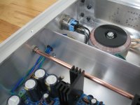
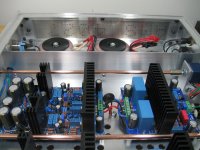
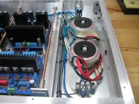
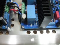
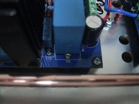
The transformers are Antek and I decided to build an EMI shield, just in case. The wires pass through it at the edge near the front panel, away from the input signal.


Attachments
-
 Bottom_detail.JPG87.8 KB · Views: 647
 -
 Pumpkin.JPG164.4 KB · Views: 629
 -
 Shunty.JPG167.9 KB · Views: 621
 -
 Pumpkin_Shunty_2.JPG250.1 KB · Views: 623
 -
 Pumpkin_Shunty.JPG240.7 KB · Views: 95
 -
 Shield_grommet.JPG144.5 KB · Views: 619
 -
 EMI_shield.JPG181.4 KB · Views: 641
 -
 Transformers.JPG204.1 KB · Views: 625

I'll contact the moderators. In the meantime, maybe you can give me an idea.
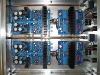
I am having a problem adjusting the Pumpkin and may be something simple, which I am missing.
The Shunty is delivering +/-36V absolutely stable. When I connect the probes to signal ground and TP1 or TP2 I get 0.114 mVDC. Yes, that is the scale, mVDC! Great, isn’t it? Well, I am not sure. Turning WR1, which according to your schematic should correct any imbalance between the J309s, moves that voltage very little. Turning WR2 I only managed to make the Pumpkin run hotter, to the point of only being able to keep my fingers on the heatsink for 3 seconds.
What am I doing wrong?
- Home
- Amplifiers
- Pass Labs
- Pumpkin Preamp - Perfect for F4