Has anyone done any crossover circuit upgrades on Q's 3050 floor speakers? I just did Elac B6.2 with the help of GR Research and Parts Express. Pricey, but it made a good speaker better. I also have a pair of Q Acoustics 3050i. Also a very good speaker, but I think it could be improved. Any help would be appreciated. Thanks, Steve
I think you need to trace the schematic. Last circuit I saw for Q Acoustics was rather better than most. Can't find it right now, though I think it was at this forum, but had impedance correction IIRC. 6" drivers are a bit more difficult than 5" usually. Are these plastic midbasses?
And yet still not what you were looking for? The way to 'upgrade' a crossover is to study the acoustic behaviour of the speaker and make sure the network is doing its job.it made a good speaker better
I'd start by measuring the speakers' response. Then also the individual drivers (unfiltered), both response and impedence. Then recreate the original filter in XSim or Vitruixcad. The resulting simulated response should be very similar to your first measurement. Make changes to the simulated XO until you're satisfied, and implement them in the original XO. Then measure the speaker again to verify your results.
good advice
Thanks for your thoughts. I am looking into the software that vyou mentioned. Need to learn all of this as this is a new project for me. Thanks, Steve
Thanks for your thoughts. I am looking into the software that vyou mentioned. Need to learn all of this as this is a new project for me. Thanks, Steve
I say this with much kindness, but if you start out in a muddle, it usually gets worse! 😀
The Q Acoustics 3050 describes several loudspeakers. A Home Cinema range, MTM tower and MT box, AFAIK.
What are we talking about here? Advice depends on circumstances.
The Q Acoustics 3050 describes several loudspeakers. A Home Cinema range, MTM tower and MT box, AFAIK.
What are we talking about here? Advice depends on circumstances.
The QA 3050i is the floorstander - it's confusing because they use rhe same name with a home theater set consisting the floorstanding speakers.
I own the Concept20 and also got curious abour possible improvements.
The enclosure - bracing - the xo - even the wiring is very well done.
The xo components are good chosen, could only throw some money in it to have some known brands in the caps but I'm more than happy with the result.
The damping might the only step for improvement but I have no known issue with these speakers in my living room.
I would start with damping and filling till they are pleasing to your ears and measurement in your room.
For most of the speakers thats a easy, affordable step up and a bice starter for inroom measurements!
OT: Got now 4x concept 20 + the concept center (40?!) As a home theater and I'm pleased.
Never had anything better for the money - the low-end must be improved but that's all.
Would love to integrate the floorstanding concepts but got no space for them 🙁
Q Acoustic
These are the specific speakers that I’m asking about.
Q Acoustics 3050i Floorstanding Speaker Pair
Thanks for asking. Steve
These are the specific speakers that I’m asking about.
Q Acoustics 3050i Floorstanding Speaker Pair
Thanks for asking. Steve
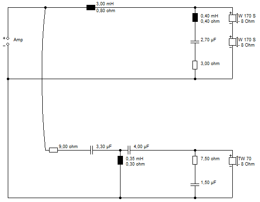
Your first step must be to look at your existing crossovers. Looks to be series wired basses judging from the impedance.
The bass section will be the bigger components. Coil and capacitor you'd think. The tweeter section will be smaller stuff. Probably a couple of capacitors and a small coil plus a resistor or two.
Can be on these lines with a LCR notch:
The bass section will be the bigger components. Coil and capacitor you'd think. The tweeter section will be smaller stuff. Probably a couple of capacitors and a small coil plus a resistor or two.
Can be on these lines with a LCR notch:
Photographs of your 3050i crossover board are required in order to judge the nature of the crossover design and the quality of the fitted components - I can't find any images on the interweb.
P.S. Unless Q Acoustics have blown the budget on the HPE (Helmholtz Pressure Equalizer) technology, I can't see them skimping on the quality of either the crossover components or the crossover design.
P.S. Unless Q Acoustics have blown the budget on the HPE (Helmholtz Pressure Equalizer) technology, I can't see them skimping on the quality of either the crossover components or the crossover design.
Last edited:
I would get an equaliser and carefully identify the problem areas. It's going to be necessary to have some information and this is better than nothing if the owner doesn't have plans to measure. How can we guess changing this component or that, unless we have some information.
@ Galu, OP has been down that road. Besides, I'd rather have an electrolytic on my tweeter any day than an incorrect value.
@ Galu, OP has been down that road. Besides, I'd rather have an electrolytic on my tweeter any day than an incorrect value.
To the OP. I also have Q3050 for many years by now. I've used them while developing some very high end electronics (as a stable frame of reference), and in case a power amp mistake is made for example (we don't melt a $10K speaker). Its a great speaker, esp for the money (unbeatable, IMO). But can we get substantially better with improved xover parts? Sure we can. Are stock, low cost parts corking up the sound? Yes, of course they are.
For example, the sand cast power resistors, those are widely used unfortunately but generally horrid IME. Do they matter? Can we do better? Dear G-d yes.
The caps- I have a cap recipe that took years to arrive at, but it's the most transparent, most out of the way cap sound I know of. Vs nearly everything else available. I put it into my friend's Crimson monoblocks recently for example (while also updating the slit foil PSU caps and shielding the transformers). It rocks. We'll apply it here too. I also was able to get WD status for these parts too, thankfully, which saves a lot of money.
The inductors. Maybe we can at least change a smaller iron core or 2 to air core. We'll see what they have done and go from there.
The wire.. Many choices and I have alot of pure/OCC Ag and Cu, etc, etc on hand, but have some new specially treated Cu wire from Audience that I'll likely look to use. The Audience interconnects and speaker wire lately are generally amazing BTW IME. Immediately noticeable vs others. They clearly have discovered some things about conductors (and caps) that matter.
Fortunately the 3050 is already bi-wireable/ampable, unlike the 3050i. Bi-wiring/amping is always a substantial upgrade in clarity, etc.
I plan to dive in soon. If interested I could update this thread. We'll see how close the transparency can get to my friend's Concept 500's. Should be interesting!
TurboTR
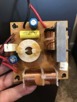
Just pick up a pair of Q Acoustics 3050s for $200 They seem to deserve the 5 star ratings from What HIFI, but when I peeked inside I was stunned by the crossover. Tiny electrolytic caps, sand cast resistors and iron core inductors. I would think a little money spent on much better components would be well spent. Has anyone done this? Anyone have an accurate schematic drawn up? The electrolytic caps are only 10uf and 6.8uf, so swapping those to some good metalized polypro caps wouldn't be too cost prohibitive. I would have only expected to see electrolytic caps in really old speakers, or in something with very high values, like my ELAC Uni-Fis. Those have 90uf, 180uf, and 250uf caps. Here are a couple bad pics of the crossover board.
Attachments


I don't know Inductor values, but at a glance, the boards have: A 5watt 1.2ohm sand cast resistor. A 5watt 22ohm sand cast resistor. A 10uf 100 volt electrolytic Cap. A 6.8 uf 100 volt electrolytic cap. A 2.2uf 250 volt no name MKT cap. As Danny Ritchie from GR Research would say: "Cheese. Really Cheesy".

It appears my attempt to revive an old post isn't getting any traction. As I read through this, it seems to me that most of the responses missed the mark of the OP. I don't think he wanted to design a new crossover with different values of components. He wanted to upgrade the incredibly inexpensive, low quality parts that are used in the original. It isn't the crossover design he is questioning, rather its execution with electrolytic caps, 5 watt sand cast resistors, and tiny gauge iron core inductors. I also think there are gains to be had with higher quality, same value components. But the original crossover board is so physically small, it would be easier, if a schematic were available, to point to point wire an entire new crossover with higher quality parts.
Including details of the 3050 would be useful: https://www.qacoustics.co.uk/q-acoustics-3050-floorstanding-speakers-pair.html
The speaker is a 2-way reflex design comprising two bass units and one treble unit. The crossover frequency is 2.6 kHz.
Since you are in possession of the crossover board, you are well placed to attempt drawing up its schematic.
Alternatively, if you provide clear photos of both the component and track side of the circuit board, someone may be able to deduce the circuit.
He did change those components.I don't think he wanted to design a new crossover with different values of components. He wanted to upgrade the incredibly inexpensive, low quality parts that are used in the original.
Was he satisfied with his results? Curious what components he changed to and if he added bypass caps. I dug into 1 of mine a bit more and found the second crossover for the tweeter circuit. The first board, mounted on the back wall of the cabinet behind the lower woofer, is only for the low frequency drivers. That has the electrolytic caps and iron core inductors. There is another board mounted on the back of the bi-wire input terminals on the back of the speaker that is the crossover for the tweeter. That has an MKP cap, a small air core inductor, and a couple sand cast resistors.He did change those components.
Attachments


Have you experience with this when done in a way that doesn't change the value of capacitance?bypass cap
Was he satisfied with his results? Curious what components he changed to and if he added bypass caps. I dug into 1 of mine a bit more and found the second crossover for the tweeter circuit. The first board, mounted on the back wall of the cabinet behind the lower woofer, is only for the low frequency drivers. That has the electrolytic caps and iron core inductors. There is another board mounted on the back of the bi-wire input terminals on the back of the speaker that is the crossover for the tweeter. That has an MKP cap, a small air core inductor, and a couple sand cast resistors.
I asked Monitor Audio for a tech drawing of my speakers crossover to get the inductor values..& they gave it to me!. ....If you don't get the inductor values, then a set of Mills 12w 1% tolerance resistors & any half decent poly caps brand (Jantzen/Claritycap/Mundorf) even their basic ones to replace those on the board would make a start..
Remove the internal wiring & use some 2.5mmCSA OFC test/measurement lead cable...very good & much cheaper than some of the branded "audio" OFC...
Ideally you want to swap out in the inductors for air cored, low DCR (I went for 1/20th of that drivers stated nominal impedance) & obviously much thicker wire gauge..
- Home
- Loudspeakers
- Multi-Way
- Q Acoustics 3050 crossover