Hi !
What is the optimal schematic to connect push-pull output transformer to the signal generator in order to properly measure frequency response? Generator is Digimess FG200 capable 7V rms, output impedance 50 Ohm. Transformer secondary loaded with 10 Ohm non-inductive resistor (I don't have 8 Ohm non-inductive). RMS voltage on secondary is being measured with oscilloscope.
Right now I simply connected transformer primary straight to the generator.
Transformer is quite bug, 3.9K 60W push-pull with cathode feedback. Leakage inductance (with 8 Ohm tap shorted) is 4.39 mH (cathode feedback off), and 4.64 mH (cathode feedback in series with primary). Top -3dB frequency is 77KHz.
With current setup its seems I can't catch up resonant frequency - there should be a resonant peak but till 260 KHz there is a just continuous drop. It makes no sense to go beyond that frequency.
12% CFB have little effect to the final numbers so IMHO it can be kept disconnected - please correct if I'm wrong there.
Thanks in advance for any suggestion(s).
The generator should have Rout = 3.9k, and the cathode windings should still be properly terminated.
HiHi !
What is the optimal schematic to connect push-pull output transformer to the signal generator in order to properly measure frequency response? Generator is Digimess FG200 capable 7V rms, output impedance 50 Ohm. Transformer secondary loaded with 10 Ohm non-inductive resistor (I don't have 8 Ohm non-inductive). RMS voltage on secondary is being measured with oscilloscope.
Right now I simply connected transformer primary straight to the generator.
Transformer is quite bug, 3.9K 60W push-pull with cathode feedback. Leakage inductance (with 8 Ohm tap shorted) is 4.39 mH (cathode feedback off), and 4.64 mH (cathode feedback in series with primary). Top -3dB frequency is 77KHz.
With current setup its seems I can't catch up resonant frequency - there should be a resonant peak but till 260 KHz there is a just continuous drop. It makes no sense to go beyond that frequency.
12% CFB have little effect to the final numbers so IMHO it can be kept disconnected - please correct if I'm wrong there.
Thanks in advance for any suggestion(s).
try to use the backward method, it is very simple with a little test setup
You can drive with a ss amp and in series to secondary a 8/10 ohm resistor. The primary can be closed to the nominal Z (3,9kohm)
In this way with the ratio of 22 ( your trafo) with 2,8 volt /8ohm, 1 watt you can get 61,6 Vrms on primary that is the effective voltage where you can check the results.
If you have a good ss amp you can check until the nominal voltage to have 60 watt; so 22 volt x 22 times you will have 484 volt that is the voltage the tubes will give at the primary.
I know about it but quite skeptical. What exactly is being measured? Backward connected transformer is just a different entity.try to use the backward method, it is very simple with a little test setup
The OT trafo is a bi-directional device ( same others)
With some time you give to the test you can see the results of the method.
This is the only way to test the stuff from a little voltage to the maximum if the setup is well implemented.
With some time you give to the test you can see the results of the method.
This is the only way to test the stuff from a little voltage to the maximum if the setup is well implemented.
If the aim is to indicate the frequency response in a particular amplifier then the driving voltage signal series resistance should be equivalent to the Ra of the driving valve being used (ie. not related to the nominal primary winding impedance). For a simple SE class A output stage, the valve Ra is typically identified in the valve datasheet (ie. triode and pentode Ra values are quite different), but for more complicated setups like UL then some calculation is needed. The 50 ohm of the signal generate is subtracted from the external resistance to achieve a net Ra value driving the primary.
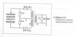
To measure a PP OPT configuration you will need to float the signal generator, or use a balanced buffer amp to interface to the OPT (where the primary CT is grounded to one side of the secondary). Each primary winding arm is driven by its valve's Ra.
The frequency response may vary for different secondary tapping settings, and how different secondary tap connections are grounded or paralleled/series in some cases, dependant on the internal winding configuration and parasitic impedances.
How high a frequency is needed will depend on the amplifiers stability performance, especially if global feedback is used, and may need to extend beyond 260kHz depending on how hi-fi you are reaching and how many dips and bumps may be occurring in the vicinity of the loop gain/phase zero crossings.
I'd caution against following Waltube's method for this type of test, as he hasn't provided a range of testing to confirm bi-directional behaviour no matter how much diatribe follows this post.
Last edited:
As wrote in the past the reverse method is simply to set.
Two resistors, one good ss amp ( commercial) one sound card with Arta or Visual Analyzer ( or Rew) ; with 24 bit/192 kHz it is possible to have an enogh bandwidht to understand the OT; it is not necessary to go at 260 kHz specially if you terminate the OT with the nominal Z
I think with 1 hour of job everyone can understand the set up
As specified more than one time the big limitation is to drive the primary with a proper signal and a proper Zout.
If the reference could be 1 w / 8ohm in this case ( as wrote) you need around 62 Vrms ( 175 Vpp) with a Zs = 3900 ohm
And this is not possible to get it with a standard generator even it is an high quality stuff.
The results I published in the past are esplicative
A lot can happen above 96kHz in a hi-fi amp, as indicated by response plots in Dixon's 1953 report https://apps.dtic.mil/sti/pdfs/AD0011593.pdf
Measurements up to 96kHz can be informative for how to manage feedback networks that influence response in the 20-20kHz audio range, but that is not where unstable conditions originate for hi-fi performance. An example of performance testing to 96kHz is in https://www.dalmura.com.au/static/Williamson output transformer measurements.pdf and indicates the differences that can occur just in secondary winding configuration, but it is what can happen above 96kHz that likely determine phase and gain margins for amplifier stability.
Measurements up to 96kHz can be informative for how to manage feedback networks that influence response in the 20-20kHz audio range, but that is not where unstable conditions originate for hi-fi performance. An example of performance testing to 96kHz is in https://www.dalmura.com.au/static/Williamson output transformer measurements.pdf and indicates the differences that can occur just in secondary winding configuration, but it is what can happen above 96kHz that likely determine phase and gain margins for amplifier stability.
To measure a PP transformer properly, you first need balanced output generator and you must respect the CT polarity to ground. If you do not respect that, weird responses might happen, capacitive roll-off can increase asymmetrically, additional resonances can occur. This depends of the transformer's construction.
Frequency response and resonances will depend on transformer construction, the Zgenerator and the Zload.
To quote a specific frequency response, you need to include the testing conditions. For tube amplifiers, output transformers are usually tested with a Rgen close to tube Rp average and speaker Rload.
Note that for frequency response testing with low voltage generator, bottom end roll-off can be higher due to the low core excitation.
The bw if 96 Khz is enough.
Then other test will be take in consideration not only the freq. answer
One of the most important is Thd vs Freq. that show mainly the performance of the trafo at mid-low frequency where the musical energy is concentrated.
The shape of the curve, with the reverse method, show the performances of the OT itself , out of the circuit for the lowest level to the maximum.
Then with the test of the entire circuit it is possible to understand how much the tube can introduce the Thd; remember that at low frequency, due the drop of inductance, the tube must deliver more current and this increase distortion
Of course the square wave is another test but must be done also at different level; at low level it can't tell us not so much. And it helps to understand if we have some resonace; but, as you know, it could come up when th FB is applied where the entire circuit is not properly dimensioned.
Regarding the old venerable test, as Radiotron, they help a lot but at that time the choice of proper test set was not available.
There are three articles of Mr. Partridge on distortion with a lot of information but the test set was very limited even the theory eas clear
Now with a few money we can set a good basic configuration to get in deep of the OT trafo only.
Could this help for pp?
https://www.ti.com/lit/ds/symlink/d...l=https%3A%2F%2Fwww.ti.com%2Fproduct%2FDRV134
https://www.ti.com/lit/ds/symlink/d...l=https%3A%2F%2Fwww.ti.com%2Fproduct%2FDRV134
One of the old method described by Partridge is to have as generator a power trafo with muliple tap for different voltage level, but the frequency is fixed, of course.
This to show the distortion.
This to show the distortion.
The bw if 96 Khz is enough.
Then other test will be take in consideration not only the freq. answer
One of the most important is Thd vs Freq. that show mainly the performance of the trafo at mid-low frequency where the musical energy is concentrated.
The shape of the curve, with the reverse method, show the performances of the OT itself , out of the circuit for the lowest level to the maximum.
Then with the test of the entire circuit it is possible to understand how much the tube can introduce the Thd; remember that at low frequency, due the drop of inductance, the tube must deliver more current and this increase distortion
Of course the square wave is another test but must be done also at different level; at low level it can't tell us not so much. And it helps to understand if we have some resonace; but, as you know, it could come up when th FB is applied where the entire circuit is not properly dimensioned.
Regarding the old venerable test, as Radiotron, they help a lot but at that time the choice of proper test set was not available.
There are three articles of Mr. Partridge on distortion with a lot of information but the test set was very limited even the theory eas clear
Now with a few money we can set a good basic configuration to get in deep of the OT trafo only.
No Walter 96 kHz is definitely not enough. Simply because many good pp amplifiers have a bandwidth greater than that and almost all of them use overall feedback.
If we look at the behavior of a transformer above 50kHz we often see resonance problems (your Fiat for example, but that was SE), the better transformers above 150kHz, the absolute best above 400kHz.
But of course there is another way, filtering hf. Just look at guitar amps and you will understand the trick.
Measuring the thd of a transformer is useless, it is already very low, especially between 100Hz and 10kHz in almost any decent transformer and also other components in the amplifier have much more thd. If you are obsessed with the thd in a transformer you need to make the Ri<< Rload. In your reverse test you just did the opposite and that turned out to be the wrong way. If you are willing to improve your circuit read the advice others gave you in previous threads.
The most important signals for music are not at the higher levels but are the lower levels. The range is about 90dB and with 1W you are not at the lower range of the transformer, even 100mW is not really low. Think in dB scales.
You are very fond of your inverse method and in a way it can be useful if you make some changes in the circuit. But mostly it is brute force and most likely limited in frequency bandwidth (much less than 100kHz-200kHz) only at 500kHz does it start to get fun. Otherwise you are never going to understand your transformer.
btw the square wave test can be done at any reasonable level unless the frequency test shows problems in bandwidth. Any skilled technician will understand.
Last edited:
If we look at the behavior of a transformer above 50kHz we often see resonance problems (your Fiat for example, but that was SE), the better transformers above 150kHz, the absolute best above 400kHz.
However testing resonance behavior under a resistive load is not enough. You need to make sure resonances won't appear under speaker loads, where in many cases impedance will rise vs frequency.
Usually resonant free square waves are achieved using dominant Ls/Cp+Cs parameter roll-off, which will mask potential resonances. However they might still appear on phase response.
For gNFB PP amplifiers, If dampened HF square response is desired, the output transformer should be designed with Cp + Cs surplus and lower Ls to guarantee the constant early roll-off with various loads. The lowering of the gNFB stage output impedance takes care of the increased interwinding capacitance.
You make it a lot harder .....
But would it be better to have a transformer with better specifications under ideal conditions or would you prefer a mediocre transformer under the same conditions?
is there a test methode what you will prefer?
btw i know stereophile test with a simulated speaker load. Without fb the results are usually horrible for se amplifiers without fb.
Secondly there are many speakers…..all different… most have also horrible distortions.
Last edited:
Yes but, if you stress and aim for gNFB stability, you need to be familiar with all potential transformer behaviors under different circumstances.
Some builders might add an RC secondary network.
Yes, I agree it's better to have the optimal transformer for your project. Personally in my work I don't see much value in transformer measurements towards importance for overall sound, but in this case, especially with secondary strapped gNFB, we can both mutually agree HF performance is not to be neglected.
It's just a reminder - a transformer that behaves well under resistive load can give surprises under speaker loads. Especially transformers designed for leakage roll-off.
Actually the ideal method would be to use a VNA (vector network analyzer) like the Bode100. It is connected to both the primary and the secondary and measures the transfer from primary to secondary, so drive issues are eliminated.
You used to be able to get low cost VNAs from Ham clubs and the like, but I haven't seen them lately. A Bode100 is not cheap, but very valuable.
But I think you can do the same with a 2-channel scope on subtract and sweeping the signal generator.
Jan
You used to be able to get low cost VNAs from Ham clubs and the like, but I haven't seen them lately. A Bode100 is not cheap, but very valuable.
But I think you can do the same with a 2-channel scope on subtract and sweeping the signal generator.
Jan

Also useable is the analog discovery2:
https://digilent.com/shop/analog-di...ope-logic-analyzer-and-variable-power-supply/
Or a picoscope with software from this site: https://bitbucket.org/hexamer/fra4picoscope/wiki/Home
For the Analogdiscovery is also a special audio software suite:
https://digilent.com/shop/analog-di...ope-logic-analyzer-and-variable-power-supply/
Or a picoscope with software from this site: https://bitbucket.org/hexamer/fra4picoscope/wiki/Home
For the Analogdiscovery is also a special audio software suite:
- Home
- Amplifiers
- Tubes / Valves
- Q: Measuring Frequency Response of PP Output Transformer