I added it here.
https://github.com/stefaweb/Q17-Amplifier/blob/main/Q17-Project-Description.pdf
Please note, there are errors on the component numbers.
iTiberius has disappeared from the surface. 😢
https://github.com/stefaweb/Q17-Amplifier/blob/main/Q17-Project-Description.pdf
Please note, there are errors on the component numbers.
iTiberius has disappeared from the surface. 😢
I've downloaded files from Tiberius's github.
https://drive.google.com/drive/folders/1v48mDzgeiGWka17qroqA9q4CpzaoyaP0?usp=drive_link
https://drive.google.com/drive/folders/1v48mDzgeiGWka17qroqA9q4CpzaoyaP0?usp=drive_link
Hello,
I am continuing my sensitivity tests of the Q17. I almost finished the 0.7Vrms (0dBu) version.
I measured the damping factor of the Q17 in passing. Which had never been done if I'm not mistaken.
We obtain a damping factor of 290 from 40Hz to 1KHz.
Regards,
Stef.
I am continuing my sensitivity tests of the Q17. I almost finished the 0.7Vrms (0dBu) version.
I measured the damping factor of the Q17 in passing. Which had never been done if I'm not mistaken.
We obtain a damping factor of 290 from 40Hz to 1KHz.
Regards,
Stef.
Attachments

Hello,
I have completed testing for the input sensitivity of 0.7Vrms (0dBu).
There is not much modification. Only resistor R17 changes from 3k3 to 5k1. This gives a gain of 5.31 for the opamp and 35 for the whole.
As a reminder, I also advise you to upgrade R17 to 47k and C7 to 2.2uF for better bandwidth linearity.
I will update my Github repository when I have done the other sensitivities (1.2V and 1.4V). There will be more modification for these two sensitivities as the opamp gain should be at minimum 4 (best is between 5 and 6).
In terms of the amp's sound signature, there is not much change. The low mid is more balanced and the bass a little firmer.
Regards,
Stef.
Attachments
-
 Q17-SQUARE-20KHz.jpg38.2 KB · Views: 78
 -
 Q17-SQUARE-10KHz.jpg37.3 KB · Views: 56
 -
 Q17-SQUARE-5KHz.jpg36.9 KB · Views: 60
 -
 Q17-SQUARE-1KHz.jpg36.4 KB · Views: 58
 -
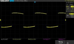 Q17-SQUARE-100Hz.jpg37.5 KB · Views: 58
 -
 Q17-SQUARE-40Hz.jpg39 KB · Views: 63
 -
 Q17-SIN-1KHz.jpg42.6 KB · Views: 60
 -
 Q17-DF-0.7v.jpg121.5 KB · Views: 70
 -
 Q17-band-2.2uF-5K1-560-dBu.jpg397.1 KB · Views: 93
 -
 Q17-spectre-2.2uF-5K1-560-dBu-1W.jpg369.2 KB · Views: 85

Is this with SMPS or linear supply?In terms of the amp's sound signature, there is not much change. The low mid is more balanced and the bass a little firmer.
Linear (an analog lab power supply) for the measures and a Q17-Mini (one pair power mosfet) stereo block with a 160VA toroid at 50Vdc on a pair of JBL L75 and a pair of Triangle Titus for the listening session. The spectrum measure is not perfect as I don't have a notch filter after the oscillator. In any case, the measurements are only there to verify that the amp is not doing anything bad, only the final sound matters.
For sensitivity, I took a margin so as not to reach the clip at 0.7V. The clip is at 27V.
Stef.
For sensitivity, I took a margin so as not to reach the clip at 0.7V. The clip is at 27V.
Stef.
Last edited:

Hi Stef1777
you mean:
As a reminder, I also advise you to upgrade R17 to 4k7 and C7 to 2.2uF for better bandwidth linearity....?
OOPs, sorry.
R16=47k (was 22k)
R17=5k1
C7=2.2uF
The R16 47k value is already up to date on the Github diagram.
Stef.
And for those who would like to have fun going bigger for C7. It's not good either. 😉
With C7=4.7uF
The maximum before it degrades too much is 3.9uF. A cheap way to turn up the bass.
With C7=4.7uF
The maximum before it degrades too much is 3.9uF. A cheap way to turn up the bass.
Attachments

Last edited:
Call for volunteers to test 1.2V sensitivity.
After having tested several ways of doing things, I suggest you test the sound result of this configuration before making it official.
The measurement data is practically the same as the 0.7V version except for the damping factor which increased to 350.
Here are the values under test for 1.2Vrms (+4dBu)
R16=47k
R17=4k75
R27=560
R6=182
C7=2.2uF
opamp gain: 5.6
overall gain: 22
Output @ 1.2Vrms = 26V
Respect the values because a small difference in resistor causes the gain to vary by a significant proportion.
I left a margin before the clip at 28V.
Let me know if you do the test.
Regards,
Stef.
Attachments


Hello,
I shouldn't lower the sensitivity any further (1.4V and 2V). This does not work (see curve examples ). I have tried several methods (including R27) and none give good results. Given that below a gain of 4 for the opamp with R17/R6, I cannot reduce it further.
Unless anyone has an opinion/idea on that.
Stef.
Spectrum at 1W.
Attachments


Hello,
Do not take into account the last 2 or 3 spectrum curves I posted. They are all bad (THD). After suspecting a bad setting of the USB interface, I agreed that through testing I ended up breaking something on the Q17 test board.
I went to get my Q17-Mini stereo block (updated 1.2V) from the living room and put it through the bench. It's OK. See the attached curve.
Sorry for that.
All I have to do now is repair the test board (Find what is broken above all). 😈
Stef.
Curve at 1W output.
Attachments


Last edited:
Hello,
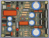
I created a maintenance version of the Q17-Mini which supports the various circuit modifications made over the past few months.
The most important is the modification of the PCB to be able to fit a 2.2uF MKP for C7. Second, I added a dual TH and SMD footprint for U2 (NDC7003P)or Q11/Q111 (2 x BP250P)). Those who are reluctant to solder SMD to make a Q17 without using an SMD component.
I built a prototype to check that everything is ok.
I had to upload the files quickly as soon as I had a little time to prepare everything.
Regards,
Stef.
Version [2.2] (31-05-2024)
- Modified C7 footprint to support 2.2uF MKP capacitor (Lead Spacing 22.5mm).
- Added double footprint for SMD U2 (NDC7003P) or TH Q11 / Q111 (BS250P).
- Added D7 and D8 zener protection (MMSZ5245C).
- Removed R33 and C20 (removed LFE at input no longer used).
- Various changes on GND and GNDPWR backplane.
- Changed C15 and C16 to 470uF.
- Added more parts on the diagram.
- Updated diagram to 2.2.
- Updated iBOM Q17-Mini-BOM file.
Attachments


Good morning,
I have uploaded the files for the new 2.2.1 version of the Q17-Mini on my Github repository.
The new board also supports an MKP Vishay 1839 for those looking for an improvement for C7.
Regards,
Stef.
I have uploaded the files for the new 2.2.1 version of the Q17-Mini on my Github repository.
The new board also supports an MKP Vishay 1839 for those looking for an improvement for C7.
Regards,
Stef.
Attachments


Hello,
I put the Q17-Mini PCB 2.2 through the test bench. Everything is OK.
Bandwidth and spectrum are still good.
Measures done at 1W output with 1.2Vrms input sensibility.
I gave you the two measurements below. Scope measurements with sine and square signals are as usual and not included.
The tests and modifications to the circuit/PCB that I plan to do in the coming weeks aim to improve the signal-to-noise ratio. We'll see if I can do it. 😉
Regards,
Stef.
Attachments


How did it workout with the WURTH Coils?Some progress. Boards are released by customs.
- Home
- Amplifiers
- Solid State
- Q17 - an audiophile approach to perfect sound