All NPN BJTs will be fine.Good to see that you have made a 405-2 kit with based on the later Quad design. I probably did not notice it because I was looking at those with the MJ15024.
Did you have any stability issues with the c5200 with a much higher Ft of 30Mhz? That's my main concern about using the MJW3281
But it does not need high-frequency triodes. Because it will be reduced to use.
But remember. Do not use MOSFET.
Although MOSFET is more attractive. Do not use Darlington NPN either. Although I have tried MJ11032. No problem was found after modifying 4148 offset. But the distortion is getting bigger.
In fact, most people have modified quad405 even worse. Not better.
I can give suggestions for modifying quad405. Is to reduce the gain. This can significantly reduce thd.
In addition, reduce the capacitance of LPF. It can reduce the high-frequency attenuation. The details are better.
In addition, do not replace the operational amplifier.
Because it's not good.
Before making a modification. We must have theoretical support.
otherwise. It reminds me of hundreds of years ago. Someone is ill. The doctor will take out the knife. Bleed the patient.
They think this will remove the disease. I don't want to judge by imagination.
In fact, quad405 has little to do with LJM.I saw it with my own eyes and heard with my own ears. Two similar boards with the LJM brand. One looked better made than the other and the better made one had a nicer sound.
I suspect the other was a copy of the original LJM
I don't even like quad405 very much. So even if some people say that the quad405 made by LJM is not very good. It doesn't matter.
I think mx50X2 is simpler. Cheaper. The performance is also much better.

The problem now is finding transistors with low transition frequency. 30mhz is considered 'low' nowadaysBut it does not need high-frequency triodes.
.Definitely agree. Changing to a MOSFET requires a lot of redesign work, especially dealing with the gate capacitanceDo not use MOSFET
Yes, the gain at the op-amp is set for a 1v RMS input vs. approximately 0.5v for the original design. Will definitely lower the noise floorI can give suggestions for modifying quad405. Is to reduce the gain
I told myself that the Quad 405 clone is going to be the last solid state amplifier that I will build.....I think mx50X2 is simpler. Cheaper. The performance is also much better.
until the itch becomes too great.
The second-hand market is stuffed with them, I jump on everything I find and I will continue until I have no more room to store them because one day maybe I will be retired and I could FINALLY look into all my projects.The problem now is finding transistors with low transition frequency. 30mhz is considered 'low' nowadays
Room for more audio stuff is relative. I believe that I have lots of room for more, but my wife seems to think otherwiseI will continue until I have no more room to store them
But for this Quad 405 clone, I have a few friends who are keen on the project. I need to find transistors for 5 pairs of this amp, so will have to settle for what's new and plentiful.
After navigating delays from work, parts shortages and missed orders, I've finally completed the Next Gen 405. Have listened to it and happy with the sound. Plenty of power to drive an authoritative bass while maintaining a rich class A character.
I calibrated the L2 inductor by using a pulse, recorded the ringing on an oscilloscope and reading the frequency. Low inductance coils are notoriously difficult to measure, and I did not have access to a proper LCR meter. The Maxwell-Wein bridge should be balanced to at least a 5% tolerance.
Next thing to do is to get a low noise ADC to do some distortion and response testing on it.
Top side of the board containing all the through hole components. As much clearance as possible for the very hot 3W R30 and R31. Four low ESR 150uf polymer capacitors right next to the output transistors to ensure sufficient current to drive transients. Also polymer capacitors don't dry out like normal electrolytics.

Bottom side - all the SMD's and the input front end. With SMD, traces can be kept very short to reduce EMI pickup, plus ground plane on other side of the board to keep things quiet.

Completed amp with power transistors mounted on the undersize on the heatsink bracket

Side view on how things fit

Heatsink bracket has similar mounting dimensions as the original Quad 405, so potentially a drop-in replacement, but more compact.

I calibrated the L2 inductor by using a pulse, recorded the ringing on an oscilloscope and reading the frequency. Low inductance coils are notoriously difficult to measure, and I did not have access to a proper LCR meter. The Maxwell-Wein bridge should be balanced to at least a 5% tolerance.
Next thing to do is to get a low noise ADC to do some distortion and response testing on it.
Top side of the board containing all the through hole components. As much clearance as possible for the very hot 3W R30 and R31. Four low ESR 150uf polymer capacitors right next to the output transistors to ensure sufficient current to drive transients. Also polymer capacitors don't dry out like normal electrolytics.
Bottom side - all the SMD's and the input front end. With SMD, traces can be kept very short to reduce EMI pickup, plus ground plane on other side of the board to keep things quiet.
Completed amp with power transistors mounted on the undersize on the heatsink bracket
Side view on how things fit
Heatsink bracket has similar mounting dimensions as the original Quad 405, so potentially a drop-in replacement, but more compact.
Two remarks:
1. I never dared to use a TLE2071 in a QUAD-405 because it has a bug that makes its supply current increase a lot when it clips to the negative rail. It was a QUAD-405 with the original Zener diode supply for both op-amp rails.
2. Using an op-amp with FET input, you can easily redesign the DC loop such that you don't need an electrolytic capacitor in the DC feedback anymore, see https://www.diyaudio.com/community/threads/redesigning-quad-405-dc-bias-loops.339643/ Mooly's simulation results in that thread are with an incorrect resistor value.
Last edited:
Hello Richbee...or even just fit the TO264 to a TO3 footprint like that:
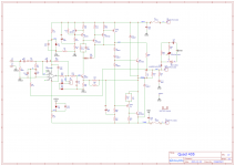
greetings what is the DC supply rails for #8 schematic is the schematic final as i hav most parts i would
like to build it.
warm regards
Andrew
I had the same concern about the TLE2071 as well, but I guessed that was going to be a rare and momentary event. I figured that a lower supply resistor, 2.7k vs 3.3k on the original, plus a 1uf decoupling capacitor would suffice, just to provide enough current for that split second and keep everything stable.Two remarks:
1. I never dared to use a TLE2071 in a QUAD-405 because it has a bug that makes its supply current increase a lot when it clips to the negative rail. It was a QUAD-405 with the original Zener diode supply for both op-amp rails.
2. Using an op-amp with FET input, you can easily redesign the DC loop such that you don't need an electrolytic capacitor in the DC feedback anymore, see https://www.diyaudio.com/community/threads/redesigning-quad-405-dc-bias-loops.339643/ Mooly's simulation results in that thread are with an incorrect resistor value.
But just in case the resistor/zener arrangement was not up to the job, I also included traces on the PCB for an active transistor power supply. Fortunately, that was not needed.
During testing, I took the amp to 80w on an 8ohm dummy load. I scoped a few points on the amp and did not remember the output of the op-amp coming close to the rails.
My preference was for an OPA134, which seemed to have fewer issues, but my choice has been limited by the current chip shortage.
Also, thanks for pointing me to the alternative DC loop design. Will read that up.
Xman, here are the Gerber files. Please use it for personal use onlyAre you willing to share gerber files. I love your design, beautiful and compact.
Attachments
Great, thank you for sharing. I am a DIYAUDIO will not use it for commercial.Xman, here are the Gerber files. Please use it for personal use only
Hello
greetings Please can you explain 120 pf has the red dots is it
to be connected if there are oscillatons ad the function of the
jumper switch connecting the two zener diodes in series.
Is it possible to post a BOM of the wattage of resistors used
warm regards
Andrew
greetings Please can you explain 120 pf has the red dots is it
to be connected if there are oscillatons ad the function of the
jumper switch connecting the two zener diodes in series.
Is it possible to post a BOM of the wattage of resistors used
warm regards
Andrew
Attachments
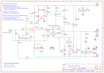
Andrew, the circuit that you referred to is different from what I used, so I can't provide you with the BOM.
As a guide, R30/31 need to be at least 3W and dropper resistors R7/R8 1w.
The circuit that you posted is similar to later versions of the Quad 405, so you can refer to photos of the board and look at the relative sizes of the resistors on the PCB. Do a Google photo search, lots of them online.
As a guide, R30/31 need to be at least 3W and dropper resistors R7/R8 1w.
The circuit that you posted is similar to later versions of the Quad 405, so you can refer to photos of the board and look at the relative sizes of the resistors on the PCB. Do a Google photo search, lots of them online.
Last edited:
Hello Altus
greetings many thanks for replying now i am following
your schematic which i have attached.
It will be a DIY effort single sided pcb with the available
components
1 ic OPA134
2 Small signal transistors A970/C2240
3 Can ZXTP23140 be substituted with C1837
rest all components exactly per schematic for the
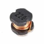
inductors i have attached pictures can they be used
Please guide me if i am wrong
warm regards
Andrew
greetings many thanks for replying now i am following
your schematic which i have attached.
It will be a DIY effort single sided pcb with the available
components
1 ic OPA134
2 Small signal transistors A970/C2240
3 Can ZXTP23140 be substituted with C1837
rest all components exactly per schematic for the
inductors i have attached pictures can they be used
Please guide me if i am wrong
warm regards
Andrew
Attachments
- Home
- Amplifiers
- Solid State
- QUAD 405 Next Gen