Here are the specs: http://www.ul.com/global/documents/...wsletters/electricalconnections/january09.pdf Basically a US GFCI will trip around 6 mA or more.. The UL filter spec limits leakage to something like 10 mA so this is where the specs collide. A microamp sensitive GFCI could easily trip from the leakage of a power transformer to its housing.
This specs collision between GFCI at 6mA and filter at 10mA is troubling. Are you sure that the filter spec is allowing leakage of 10mA common mode? I could see where it might allow 10mA differential mode, and that might be just reactive, but it is hard to see they would allow the common mode scenario (to which the GFCI is sensitive) to be that much.
BTW, I am assuming that the GFCI will trip on reactive common mode currents as well as resistive common mode currents, but I'm not certain.
For reference, I think a 0.05uF capacitor will pull about 2mA of reactive current at 60Hz and 100V.
Cheers,
Bob
Bob:
I went back and checked. I was wrong, the leakage current is 3.5 mA for a filter. Its different for a surge suppressor (can't find my copy of UL1449) but as you can see the limits are pretty close. I think the largest line to ground cap you can use is .1 uF and if you have MOV's that needs to be scaled down. The GFCI can't tell reactive currents from resistive (nor can your body. . .).
Here are some references: http://www.raymondemc.ca/resources/UL1283.pdf http://www.psma.com/ul_files/forums/safety/estguide2.pdf. The UL spec is an intro into how thorough safety testing can be.
How was IT measured? Did you run varying amounts of current to ground until it tripped? The test button on the GFI does this --- places a spec'ed amount of leakage current from H to G thru the circuit and it should trip.
[I have my copy of the UL1449]
So when making your line transformer isolation-filter be sure the value of any C to ground produces less current than is the safe maximum. Afterwards a GFI can be used for C fault or other leakage fault protection.
-RNM
[I have my copy of the UL1449]
So when making your line transformer isolation-filter be sure the value of any C to ground produces less current than is the safe maximum. Afterwards a GFI can be used for C fault or other leakage fault protection.
-RNM
Last edited:
Bob:
I went back and checked. I was wrong, the leakage current is 3.5 mA for a filter. Its different for a surge suppressor (can't find my copy of UL1449) but as you can see the limits are pretty close. I think the largest line to ground cap you can use is .1 uF and if you have MOV's that needs to be scaled down. The GFCI can't tell reactive currents from resistive (nor can your body. . .).
Here are some references: http://www.raymondemc.ca/resources/UL1283.pdf http://www.psma.com/ul_files/forums/safety/estguide2.pdf. The UL spec is an intro into how thorough safety testing can be.
Thanks for looking into that, Demian. I agree, 3.5mA is still uncomfortably close. BTW, just the other day I was trying to use a perfectly good Variac (I thought), plugged it into a GFI'd circuit I had not used it on before, and it tripped it.
Cheers,
Bob
Hello Bob, I expect the leakage of your Variac just tipped the GFI over the edge....... BTW, just the other day I was trying to use a perfectly good Variac (I thought), plugged it into a GFI'd circuit I had not used it on before, and it tripped it.
Cheers,
Bob
It is likely that you have other loads on the line that that are pushing the GFI close to threshold.
From experience, this can be a big problem in offices for example.....plugging in one more PC trips the breaker because of leakage currents, not load currents.
Dan.
interesting read here http://www.raylectronics.nl/pdfs/Balanced_thinking.pdf
and a schematic here: http://www.raylectronics.nl/pdfs/Balanced_filter.pdf
on balanced mains filters (240V)
and a schematic here: http://www.raylectronics.nl/pdfs/Balanced_filter.pdf
on balanced mains filters (240V)
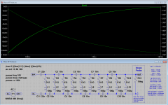
") I think that the circuit as attached is a usable probe for frequencies of 10Khz and up. I will order these parts if this looks like a usable probe to you all. As I said, I just want to know
I think that the circuit as attached is a usable probe for frequencies of 10Khz and up. I will order these parts if this looks like a usable probe to you all. As I said, I just want to know 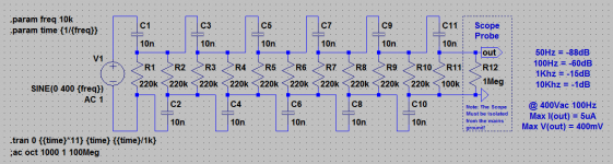
It would work but there are easier ways that are safer. You use a transformer with suitable bandpass coupled through a small cap. I think I have details somewhere. Its in the manual for this Oneac line viewer: OneAC Line Viewer | eBay
For testing of audio gear, it is usually grounding issues which cause the most problems. esp with USB powered ADC and single-ended circuits with common grounds.
However, if you think you have an EMI/RFI or other issue then filtering or removing the source of interference is needed also.
BTW- Some other test equipment I use is to verify NEC code. A couple other instruments I have on hand are made by IDEAL 'SURETEST'. Models I have are ST-1THD and 61-165. It tests for time it takes to trip the GFCI and AFCI and the trip current used is 6mA. Of course, the GFCI may trip at a lower level but it MUST trip with 6mA to meet NEC code.
This is a max safe level based on female levels (6-7mA) of current that will produce a no release control of your grip/muscle. But this protection is only for circuit component failure issues. Nothing to do with measuring and testing for low noise/ harmonic distortion levels.
Thx-RNMarsh
Last edited:
interesting read here
*******
a schematic here: http://www.raylectronics.nl/pdfs/Balanced_filter.pdf
on balanced mains filters (240V)
The schematic has a typo or error.
It labels the output as 'L' & 'N'. Yet the circuit does not have a Neutral.
The circuit output does not have a 'Grounded (current carrying) Conductor' aka 'Neutral'.
It should be:
L1
PE
L2
On second thought:
There may be more labeling problems than that.
Let me think some more.
Last edited:
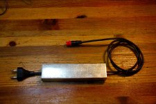
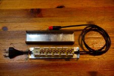
Be careful of the common BNC ground on the secondary of the PowerVAR BCN connector and make sure it doesnt connect to the input side AC ground thru leakage or direct but inadvertant connnection; Your scope or meter connected to the monitor output(s) must still float and not get connected back to the input ground.
Another way to see what noise there is on the ac line is with a non-contact current probe. I also use various current transformers (CT's) and a DC-50MHz clamp-on current probe made by TEK (P6042) to be sure there is no ground paths during test and measurement. Either way, outputs then go to a spectrum analyzer to determine the freq involved.
THx-RNMarsh
Last edited:
The schematic has a typo or error.
It labels the output as 'L' & 'N'. Yet the circuit does not have a Neutral.
The circuit output does not have a 'Grounded (current carrying) Conductor' aka 'Neutral'.
It should be:
L1
PE
L2
On second thought:
There may be more labeling problems than that.
Let me think some more.
Kevin,
In my part of the world it is common to use the labels L and N for what you call L1 and L2. (Might even be an EU directive, not sure).
So it's not a typo, and in any case, your linked circuits are clear to what's what.
jan
Part of using a low cost ADC for tests is also the pre-notch filter to keep the ADC in its optimum range.
I picked up -- from EBay -- an HP 334 just to use/modify its variable notch filter for use with ADC. These instruments are less than $USD100 and typically go from 80-90 to <200$ range.
Thx-RNMarsh
I picked up -- from EBay -- an HP 334 just to use/modify its variable notch filter for use with ADC. These instruments are less than $USD100 and typically go from 80-90 to <200$ range.
Thx-RNMarsh
Very nice work. Be careful, the scope chassis will be at 1/2 the line voltage (120V) and has low enough impedance to give quite the jolt. I would strongly recommend a transformer coupled output before you are finished with this.
The circuit looks kind of like a Kelvin Varley divider for AC.
The circuit looks kind of like a Kelvin Varley divider for AC.
- Home
- Design & Build
- Equipment & Tools
- QuantAsylum QA400 and QA401