I put a 10k 5W resistor in parallel with R38 for a final resistance of 7.6k and installed a string of three 100V zeners. Left R58 at 4.7k and installed zeners there too. Voltage settles at 326V after the zeners warm up (get up to 70C). Better than the 380V the LND were seeing before, and it will clamp any voltage spikes.
Mounted an LND250K1 on an adapter and threw it in Q2. Verified that it's functioning properly and then toggled the switches for CH1/CH2, Boost, and power a bunch of time. It's still working. Even a 50Vrms output of Q2 looked good. A 1kHz tone sounds clean now.
Guess I'll call this a win for now and give the amp back. If he has a trouble with it in the future, I have a lifetime supply of real LND150N3 on the way.
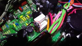
Attachments

Well, that success was short lived. He got about 5 minutes out of it before Q2 went bad again.
I don't get it. Vdd is regulated now, so can't blame high voltage/spikes, and the gate has 12V zeners to protect it. Wtf is going on.
I don't get it. Vdd is regulated now, so can't blame high voltage/spikes, and the gate has 12V zeners to protect it. Wtf is going on.
More observations. The "clean" channel only has a clean output with the tone control (VR9) all the way down. The signal gets nasty fast when you turn it up at all. A lot of noise/hiss.
I managed to kill a few more parts by probing from ground to drain on Q1 and Q2 with my meter to measure the voltage. It causes a lot of crackling/popping when I do. Probing the drain of Q1 killed Q2.
Maybe one of the film caps is bad (C25, C26, C27, C30?), I don't know. I would need to take the board out to desolder and test them.
I'm back with more ramblings. Playing around with things more, I noticed that when switching back and forth between CH1/Ch2, the CH2 signal would be inconsistent. It either wouldn't be there at all, or it would be distorted with varying output voltage.
It appeared at first to be bad relay contacts, so I went through the trouble of replacing all 6 relays. They were low quality Chinese relays with AgCdO contacts (not great for signal switching), which only bolstered my assumptions. I put in sockets and installed some old stock, Swiss made, Axiom C93416 relays with AgNi gold plated contacts. Well, that didn't fix a damn thing.
Being able to remove the relays helped me find the actual problem though. The clean channel volume pot is bad (VR7). Never seen a pot failure like this before. If I measure between ground and output, I get the full resistance sweep up to 250k and back down to ground. The input measures open-circuit to output and to ground. The track has to be broken right at the end; that's the only thing I can think of.
It was a nightmare taking the board out and putting back in. Now I get to do it again after trying to track down a suitable replacement pot.
No, VR8 is the "Clean Gain" pot on the input of Q1. VR7 is "Clean Volume" on the output of Q2.
I removed the pot and checked it. There is no continuity between the input terminal and the resistive element. The element is intact all the way to the terminal though. It's the type with the terminals that are crimped to a phenolic wafer. It's crimped tightly and not loose at all. A very strange failure; probably a manufacturing defect. Not something I've seen before.
I've ordered an Alpha A250k replacement. Shaft is a little longer, but I can trim it down if need be.
Thanks. I missed that in your post. Can you post a schematic that shows more of the circuitry from the output of that pot? Is it going to the tube stage?
From your tests it needs to be fixed. I am trying to understand why that blows the LND150. Hoping for you that there aren't other bad components. Did you test VR9?
Steve
From your tests it needs to be fixed. I am trying to understand why that blows the LND150. Hoping for you that there aren't other bad components. Did you test VR9?
Steve
something is killing it.
looking at old scope measurements see ringing and weird waveform
appearing to have excessive current.
intermittent zeners or coupling caps 26 , 27
otherwise current seems high anyways when working
but any other issues would cause it to cook quickly.
looking at old scope measurements see ringing and weird waveform
appearing to have excessive current.
intermittent zeners or coupling caps 26 , 27
otherwise current seems high anyways when working
but any other issues would cause it to cook quickly.
Last edited:
The PDF attached in my first post is the entire schematic. The output of VR7 goes directly to relay RL5, which I didn't test thoroughly enough and assumed was defective because the symptoms didn't match a pot failure in my mind.Can you post a schematic that shows more of the circuitry from the output of that pot? Is it going to the tube stage?
I removed and tested C26 and C27 @1kHz 1Vrms.
C26 - 22.98nF, Z=6.9kΩ, dissipation 0.4%
C27 - 46.9nF, Z=3.4kΩ, dissipation 0.6%
Dc blocking caps?
AC signal might be on the low side.
Otherwise I would expect those caps seeing 200 + volts
where likely to be leakage
AC signal might be on the low side.
Otherwise I would expect those caps seeing 200 + volts
where likely to be leakage
After a little mishap at the post office, I finally got my package of genuine LND150N3-G. I replaced the bad pot and it's working, for now. Also added a 1k gate stopper right at the gate of Q2. The 1k resistor on the PCB is significantly further away than for Q1 and Q3. I don't know, something makes Q2 cranky.
While the signal level of the CH2 appears to be normal, it has a lot of noise compared to the CH1. CH1 is all the tubes + the Q3 LND150 and it's super clean. I noticed that Q3 has a 10pf capacitor across the 33k drain resistor to limit the bandwidth, while Q1 and Q2 don't. I'm thinking of adding 3.3pF across the drain resistors of Q1 and Q2 to see if it cleans things up.
While the signal level of the CH2 appears to be normal, it has a lot of noise compared to the CH1. CH1 is all the tubes + the Q3 LND150 and it's super clean. I noticed that Q3 has a 10pf capacitor across the 33k drain resistor to limit the bandwidth, while Q1 and Q2 don't. I'm thinking of adding 3.3pF across the drain resistors of Q1 and Q2 to see if it cleans things up.
- Home
- Live Sound
- Instruments and Amps
- Randall Satan/Thrasher 50 Clean Channel Problem (LND150)