I can find no reference to any input protection diodes for the 4562 whereas chips like the NE5534 and others specifically mention such protection.
The data sheet for the 4562 says:
So I would say no diodes in the sense you mean.
The data sheet for the 4562 says:
These devices have limited built-in ESD protection. The leads should be shorted together or the device placed in conductive foam
during storage or handling to prevent electrostatic damage to the MOS gates.
So I would say no diodes in the sense you mean.
Conclusions 2-3 and 5-6.I'm not exactly following what you mean by diode ringing mode
Attachments
Ah, so you are measuring between the inputs using the diode range. I wouldn't be so sure that is proof of any protection tbh. You could be reading through all sorts of internal circuitry and also 'parasitic' junctions that appear under certain conditions (no power applied etc)
A simple check is to configure the opamp as a comparator and just set two different voltages on each input. If there are diodes present between the input pins then you would not be able to set voltage differences of more than your -/+ 0.8 volts. The opamp must be correctly powered though.
Also remember protection can be between the input pin and rails (supply pins) to prevent inputs being taken over the rail voltage whatever that may be. Those would be referred to as clamping diodes.
Whether the 4562 has anything like that I wouldn't like to say but I'd be 99.99% sure there is no clamping between the inputs.
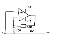
This is understandable. I want to check 4562 for originality. Is it possible to do this using this scheme by looking at the offset?A 4562 should work in your original circuit
Originality... things to check are the current consumption into each supply pin which should be around 10 to 12 milliamp. Some lesser opamps like the 4558 or 1458 are much lower.
A check on bandwidth is an essential really using a scope and signal generator with the opamp configured as a proper gain block. Square wave testing is very revealing.
Another check is DC offset with the opamp configured similar to your circuit but with the 100 ohm removed and the 10k shorted out. The offset should be really low. Now add a series resistor to the + input (such as a 1 meg) and check the offset. I would have to calculate what to expect using the data sheet but it should be much lower than for example a 5532. The offset is caused by the input bias current developing a voltage across the 1 meg and the 4562 bias currents are magnitudes lower than a 5532 for example.
Ultimately the best check has to be buying from authorised suppliers")
A check on bandwidth is an essential really using a scope and signal generator with the opamp configured as a proper gain block. Square wave testing is very revealing.
Another check is DC offset with the opamp configured similar to your circuit but with the 100 ohm removed and the 10k shorted out. The offset should be really low. Now add a series resistor to the + input (such as a 1 meg) and check the offset. I would have to calculate what to expect using the data sheet but it should be much lower than for example a 5532. The offset is caused by the input bias current developing a voltage across the 1 meg and the 4562 bias currents are magnitudes lower than a 5532 for example.
Ultimately the best check has to be buying from authorised suppliers
Yes it does.Guys, tell me, does the LM4562 have protective diodes at the inputs?
The LME49720 aka LM4562 are PNP input with bias current compensation and DO have back-to-back input diodes.
I confirmed this at the TI E2E forum as well as having tested it as a peak detector and comparator which is a function it cannot perform.
https://proaudiodesignforum.com/forum/php/viewtopic.php?p=7393
https://e2e.ti.com/support/audio-gr...49720-and-lme49860-differential-input-diodes/
https://e2e.ti.com/support/audio-gr...7540/lm4562-topology-and-return-current-paths
Last edited:
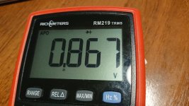
In general, I measured my 4562. The supply voltage is +/- 15 volts. The positive inputs are closed to the zero wire through a 1 MegaOhm resistor. The negative inputs are closed at the output. The current consumption in such a binding of both op-amps = 10 milliamps.
Offset at the outputs:
Op-amp No.1: 1st channel: -2.3 millivolts, 2nd channel: +4 millivolts.
Op-amp No.2: 1st channel: -9 millivolts, 2nd channel: -17.6 millivolts.
What do you say, dear ones?
Offset at the outputs:
Op-amp No.1: 1st channel: -2.3 millivolts, 2nd channel: +4 millivolts.
Op-amp No.2: 1st channel: -9 millivolts, 2nd channel: -17.6 millivolts.
What do you say, dear ones?
It sounds in the right ballpark.
Data sheet gives 10nA as typical input bias current (but can be up to 72nA worst case) and that would develop 10E-9*1E6 across the resistor which is 10mv. I just tried it for real with a 4562 and got +8mv and +6mv at the output. I would have expected the polarity to be consistent though.
(Your meter will pull the input voltage down as you try and measure it)
Ok, thanks.Yes, it's a low pass with F(-3dB) ≈ 34Hz so it will reduce supply ripple significantly.
Hm... Is it possible to increase the capacitors C121/C 122 to 100-220 uF?Yes, it's a low pass with F(-3dB) ≈ 34Hz so it will reduce supply ripple significantly.
- Home
- Source & Line
- Analog Line Level
- Replacement 4559