In high impedance non-inverting low gain applications (today's version of) OPA827 and especially OPA1641 appear to be even better than OPA828 and all of them beat OPA627 in distortion, see https://www.diyaudio.com/community/...jfet-input-op-amps.264797/page-3#post-6977701
Of course it can. Ever heard of common emitter/source output stages rather than common collector/drain outputs that you are referring to?An opamp cannot possibly do rail to rail. There are at least voltage drops in the drivers, Vce(sat) in the output pair, and a further drop in the emitter resistors of the output pair. So you ultimately be limited to at least 2V between voltage rails and peak output voltage. So for example if the rails are +/-15V the maximum output swing will be +/-13V or very close.
An opamp cannot possibly do rail to rail. There are at least voltage drops in the drivers, Vce(sat) in the output pair, and a further drop in the emitter resistors of the output pair. So you ultimately be limited to at least 2V between voltage rails and peak output voltage.
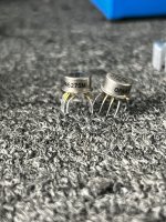
I happen to have a dozen MC33202 dual opamps in my parts drawer. Datasheet attached below.
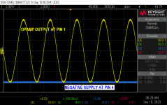
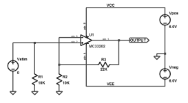
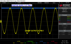
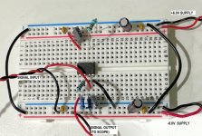
I got out my solderless breadboard and put together a little noninverting amplifier with a gain of +3.2 volts per volt; schematic and photo below.
A bit of fiddling with the signal generator's amplitude setting, allowed me to take the two scope photos shown below. The output signal on my solderless breadboard swings all the way up to the top rail, and all the way down to the bottom rail. OnSemi's datasheet talks about this, for example, in Figure 9.
Attachments
Well - colour me surprised! I really was not aware that a bipolar opamp could do that.
In fact there is (and I'd forgot - my bad) a whole thread here about the TI CMOS OPA1656, which (apart from a somewhat high 1/f frequency) pulls the same stunt of rail to rail, and is a seriously high performance standard https://www.ti.com/lit/ds/symlink/opa1656.pdf
In fact there is (and I'd forgot - my bad) a whole thread here about the TI CMOS OPA1656, which (apart from a somewhat high 1/f frequency) pulls the same stunt of rail to rail, and is a seriously high performance standard https://www.ti.com/lit/ds/symlink/opa1656.pdf
The key enabler of R2R output is the Monticelli output stage -https://x.artofelectronics.net/wp-content/uploads/2019/11/4xp11_RR_op-amps.pdf
I would consider 200 mV close enough for government work - especially for audio. ") But, yeah.... If you want to go all the way to the rail you do need to look in the General Purpose section of the data book.
But, yeah.... If you want to go all the way to the rail you do need to look in the General Purpose section of the data book.
Also note that not all opamps accept rail-to-rail inputs. If you want an opamp that can handle whatever you throw at it and and provide a rail-to-rail output, you need to ensure that it's rail-to-rail on both the inputs and the outputs.
Tom
But, yeah.... If you want to go all the way to the rail you do need to look in the General Purpose section of the data book.Also note that not all opamps accept rail-to-rail inputs. If you want an opamp that can handle whatever you throw at it and and provide a rail-to-rail output, you need to ensure that it's rail-to-rail on both the inputs and the outputs.
Tom
And if its not mentioned, its likely got phase reversal issues... Its not something to boast about!Phase reversal is usually mentioned in the datasheet.
... and check if the transition between the main input stage and the helper input stage is not corrupting your signal. Many R2R-input opamps have quite degraded specs when the helper stage becomes active, the most offending one is a large change of input offset which results in a lot of distortion when the signal traverses the transition region.Also note that not all opamps accept rail-to-rail inputs. If you want an opamp that can handle whatever you throw at it and and provide a rail-to-rail output, you need to ensure that it's rail-to-rail on both the inputs and the outputs.
Be careful with some IC's and using adapters, the extra capacitance of the adapter can cause some IC's to oscillate. Years back at a former job we tried using an IC sockets for some IC's validation and some IC's would oscillate, we remove the sockets after racking our brains out why they were failing when they had worked in other boards without sockets. We tried the same IC in a prototype board with no socket and it was working fine. So we directly soldered the IC's to boards and Oscillation was gone. This was repeatable. It drove us nuts trying to figure out why that was happening when it shouldn't have.
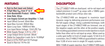
@Mark Johnson, LT1498, not that impressive. They don't even show Vos vs Vcm plot so we don't know how the transition looks like, only Ib vs Vcm which has that nasty step change which will cause trouble with unmatched source impedance.

OPA192 (FET input) looks better and they show the Vos vs Vcm transition:

Compared to OPA2156 (R2R-input variant of OPA1656) which would fulfil the LT1498's 1.3mV spec wrt to Vos shift at +-15V:

OPA192 (FET input) looks better and they show the Vos vs Vcm transition:
Compared to OPA2156 (R2R-input variant of OPA1656) which would fulfil the LT1498's 1.3mV spec wrt to Vos shift at +-15V:
Be careful with some IC's and using adapters, the extra capacitance of the adapter can cause some IC's to oscillate.
You'll never find a data sheet that actually recommends using sockets or adapters.
It's left to the user to determine whether these will cause problems in their application.
0.5 mV VOS is not exactly anything to write home about these days. It seems everybody does 100-200 µV without breaking a sweat. Auto-zero opamps like the LMP2021 gets you to ±5 µV worst case, -400 nV typical. There might be better ones out now. The '2021 is over 15 years old now.check this one:
There's no doubt the performance will change some once the input stage changes from the main pair to the helpers, but I'd argue that the performance shouldn't go completely off the rails (pun mostly unintended...
). If it does I'd consider it a design flaw .... but that's me.Tom
- Home
- Design & Build
- Parts
- Replacement for OPA627?