I noticed there's a decent amount of views on this thread, so I thought I'd post my current progress with proper voltage measurements, in case anyone is planning on giving this a go themselves.

At the moment I'm rolling with a positive grid since cut-off is only about -0.5V or so but with a grid bias of -0.25V its far too easy to hit cut-off, even with weak pickups. An attenuator could be used to bring the input signal down to scale with standard Fender input stage cut-off, but I think doing the same with the second triode would make it difficult to overdrive to the same effect.
As it is the sound is never "clean", being a positive grid, but always rather warm and harmonic-ey. With my humbuckers it starts to break up with Volume pot at 50% and pretty normal sounding hard overdrive towards 100% (I think).
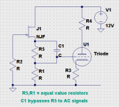
I'm still looking to do the best approximation of a Champ AA764 I can with 12V so as always I'm open to suggestions. In particular if anyone has advice on how to best implement the 34k/200pf low-pass filter, whether on the source follower or first triode, I'd appreciate it.
At the moment I'm rolling with a positive grid since cut-off is only about -0.5V or so but with a grid bias of -0.25V its far too easy to hit cut-off, even with weak pickups. An attenuator could be used to bring the input signal down to scale with standard Fender input stage cut-off, but I think doing the same with the second triode would make it difficult to overdrive to the same effect.
As it is the sound is never "clean", being a positive grid, but always rather warm and harmonic-ey. With my humbuckers it starts to break up with Volume pot at 50% and pretty normal sounding hard overdrive towards 100% (I think).
I'm still looking to do the best approximation of a Champ AA764 I can with 12V so as always I'm open to suggestions. In particular if anyone has advice on how to best implement the 34k/200pf low-pass filter, whether on the source follower or first triode, I'd appreciate it.
If you want a more-negative grid bias, you have to either increase the voltage on the anode, or decrease the current through the triode, or do both.At the moment I'm rolling with a positive grid since cut-off is only about -0.5V or so but with a grid bias of -0.25V its far too easy to hit cut-off, even with weak pickups.
Suppose you choose the first option, there's lots of room between your current 12 volt B+, and the nominal 100 volts or so the tube was designed for.
For instance, a lot of HP inkjet printers use an external, 32 volt, switching power supply. These power supplies tend to turn up in thrift stores, and since nobody wants a 32V power supply, they are usually priced very cheap.
Since the switching frequency is many kHz rather than 60 Hz, it's trivially easy to filter off any residual ripple voltage, and get a clean 30 volts or so for your preamp. This is low enough to be safe for most JFETs, and may be high enough to make your submini triodes a lot happier than they are now.
If you decide to go for the second option (lower the current through the triodes), all you have to do is increase R5 (and R13, once you have the right value worked out). You could swap in larger and larger resistors, until Vgk settles down to a suitable small negative voltage.
In situations like this I normally double the value of the resistor each time - you're starting with 10k, so try 22k, 47k, 100k, 220k, et cetera, until Vgk ends up negative and at least a volt.
Once your find the right R5, you'll have to increase R4 correspondingly, which will drop the anode voltage, and may force you to increase R5 some more. But sooner or later you'll converge on acceptable values for both.
Why not between the input JFET and first triode? (See attached schematic.)...if anyone has advice on how to best implement the 34k/200pf low-pass filter, whether on the source follower or first triode, I'd appreciate it.
This assumes the triode is properly biased, negative voltage on the gate, perhaps achieved using one of my previous suggestions in this post.
-Gnobuddy
Attachments

If you want a more-negative grid bias, you have to either increase the voltage on the anode...
My goal is a circuit that can be used as a guitar pedal or as a mini-head. Currently I have a 12V (max) TDA2030 module that I can fit inside a larger stompbox; a second jack will skip the module for output to an amp. I could run two supplies and attenuate the output before the TDA2030 module (and the other output), but that would mean either a second regulator or possibly a charge pump, but it is possible and probably would extend the negative Vgk range before cut-off.
or decrease the current through the triode
As long as I can make up any lost gain with the MOSFET that's fine, however from Merlin Blencowe's measurements at 12V the 12AU7 has a Vgk cut-off only -0.5V and that has held true for the 6111. So I don't think reducing the current will change that problem for me.
An externally hosted image should be here but it was not working when we last tested it.
I'll test a 6111 with some higher anode voltages and see how low Vgk cut-off is, but I think I might just live with a positive bias. I'll try that filter before the triode, thanks! And thanks for your suggestions in general.
Ah. Sorry, I missed that earlier. Forgot it, actually, because you explained that in your very first post on this thread, which I read quite carefully at the time.My goal is a circuit that can be used as a guitar pedal or as a mini-head.
I think (-0.5V) is better than (+0.25V), n'est-ce pas? Or am I misunderstanding something?...from Merlin Blencowe's measurements at 12V the 12AU7 has a Vgk cut-off only -0.5V
I looked up Merlin's white-paper, and he has 33k cathode resistors, where you have 10k...
I think it'll help, you know. The physics of electrons boiling off a hot cathode tells you there will be some electrons with much higher energy than average, but these will make up only a rather small fraction of all the electrons. Still, there are such unbelievably enormous numbers of electrons boiling off that cathode, that even a few percent of them is an enormous number.I don't think reducing the current will change that problem for me.
All this means that there will still be a (smaller) cathode current, even when Vgk is sufficiently negative to stop most of the electrons dead in their tracks.
It's not easy to read that on Merlin's graph, but if you could expand the y-axis, you'd probably see it.
If the circuit is still at the breadboard stage, it's easy enough to swap in a bigger cathode resistor (such as the 33k Merlin used), so why not give it a quick try? My prediction is that Vgk will go more negative than its current value.
You're quite welcome. 🙂...I might just live with a positive bias. I'll try that filter before the triode, thanks!
If bias is positive, and there is appreciable grid current flow, that series filter resistor will drop voltage across it, which will affect both the DC operating point, and the distortion signature, of the signal emerging from the triode.
This may or may not turn out to be a bad thing, in terms of how it sounds. But keep an ear open for it!
-Gnobuddy
Well I tried some combinations of higher resistors on the anode and cathode and got a Vgk of about -0.30V but it definitely farted out at about -0.5V or -0.2ish relative to the grid bias. It may be that at a lower anode voltage those high energy electrons just aren't being attracted enough by the plate to pass the grid (?), although I wasn't aware of that phenomenon at all.
The reason I went for an even higher bias was that I figured if I was in the positive anyways, I might as well aim for that second linear region. Since Vgk of 0 is right in the middle of two linear regions it seems like the worst spot to be, but maybe I'm wrong.
The reason I went for an even higher bias was that I figured if I was in the positive anyways, I might as well aim for that second linear region. Since Vgk of 0 is right in the middle of two linear regions it seems like the worst spot to be, but maybe I'm wrong.
Ah well, your reality has trumped my hypothesis. 😀...got a Vgk of about -0.30V but it definitely farted out at about -0.5V or -0.2ish relative to the grid bias.
(Which is as it should be, the idea that experiment trumps hypothesis is a major part of the scientific method. It's the thing that keeps science honest, unlike, say, philosophy, where leading practitioners spent several hundred years arguing about how many angels could dance on the head of a pin.)
Perhaps you're right, I wouldn't know, I have no experience operating valves with positive Vgk.Since Vgk of 0 is right in the middle of two linear regions it seems like the worst spot to be.
Aside from the normal desire to help, I also have a personal interest in this preamp project. A guitar amp that sounds good and only weighs as much as a dictionary would be very welcome, as I'm tired of hauling around as much music gear as I do.
I already play through what is essentially a powered speaker, so something like the preamp you're working on might be a good starting point for what I'm looking for.
Are you planning any kind of tone controls as your project evolves?
-Gnobuddy
Member
Joined 2009
Paid Member
There's a guy at my work that'd be interested in this project - where are you two located (I'm in KW, Ontario) ?
I'm on the other coast. In the Fraser valley, close enough to Vancouver to have ruinously high real-estate prices and cost of living, but not close enough to benefit from any of the advantages of a big city. 🙂There's a guy at my work that'd be interested in this project - where are you two located (I'm in KW, Ontario) ?
There have been at least two fairly recent diyAudio threads your co-worker might find interesting. One was about an all-FET guitar amp that supposedly sounds quite "tubey". The other was about (valve) output transformerless guitar amps, which, it turns out, can sound quite "tubey" (a YouTube video was linked), even though many people believe the output transformer is a vitally important part of a guitar amp's sound.
Since we now know that the output transformer isn't, in fact, a vital part of a guitar amps sound, that opens up the possibility of using a clean solid-state power amp with no sound of its own, preceded by a preamp that uses either JFETs or valves to get the sounds we guitarists want.
Which is where this thread comes in...Andyholmes has thrown in the additional wrinkle of using low DC voltage on the valves. Which, like everything else in engineering, has both advantages, and disadvantages.
-Gnobuddy
Gnobuddy said:Ah well, your reality has trumped my hypothesis. 😀
Still, was worth a shot. Although you can hear the positive grid/grid clipping in there, it really just makes it sound warm and accentuates the tube quality. Still fairly clean in other words.
Gnobuddy said:Which is as it should be, the idea that experiment trumps hypothesis is a major part of the scientific method. It's the thing that keeps science honest...
If that weren't the case I could just copy/paste from LTspice onto my breadboard though 😛
Gnobuddy said:Are you planning any kind of tone controls as your project evolves?
I've been thinking about that. Two things:
1) The 2-knob Fender tone stack from the AA764 Champ I'm pseudo-cloning is pretty lossy, but that's probably trivial to make up with the MOSFET stage.
An externally hosted image should be here but it was not working when we last tested it.
2) Although it has separate Bass/Treble controls, it has a fixed mid-cut so really isn't that much more versatile than a Big Muff Pi style tone (since more treble means less bass anyways)
So I'd be open to suggestions. Possibly the two-control fender style with a switch to control the mid-cut, or maybe Jack Orman's modified BMP tonestack which has a dB loss right in the middle of those two and both of those keep the total knob count down to three. I'd be open to suggestions here too.
For reference this is the TDA2030 module I'm using. It seems "too cheap" but I can confirm it works as advertised, and at ~$1 each it's hard to complain.
Bigun said:There's a guy at my work that'd be interested in this project - where are you two located (I'm in KW, Ontario) ?
Get him to sign up and pitch some ideas! I'm out Vancouver way as well, Langley for those more familiar.
Member
Joined 2009
Paid Member
This is definitely fascinating and I like the low voltage tubes approach.
My buddy says he likes to play and won't build so he's not gonna sign up unless something compelling comes out of this but I may be able to get him hooked once it's further along.
The funny thing, I was pushing him to try his hand at making something last week and I suggested low voltage tubes feeding a cheap class-D amp off ePay. And then I found this thread 😀
Bigun said:I suggested low voltage tubes feeding a cheap class-D amp
There are definitely some tantalizing class-D amplifiers on ebay, the catch in my books is the loads the advertised wattages apply to. The PAM8302 can do 2W, but only into a 4R speaker; the XPT8871 says it will do 3W into 4ohms, but doesn't say anything about 8ohms, although the datasheet I "read" was in chinese (probably). The TDA8932, or maybe even the TPA3110/3116/3118, might be worth looking to though.
The reason I've been using the TDA2030, is that it's a 30 year old, tried, tested and cheap chip. Actually, I think I read someone on this forum saying they helped design it.
That has actually worked perfectly for me a few times. Most recently, I designed a four-opamp audio function generator, with a diode shaping network to turn the triangle wave into a sine wave. Some of the resistor values had to be fine-tuned in LTSpice to get the sinewave distortion low enough.If that weren't the case I could just copy/paste from LTspice onto my breadboard though 😛
Amazingly, the thing worked perfectly right off the bat when I built it. I had put in trimpots for the critical resistors, but they ended up set pretty close to the values in the LTSpice model.
LTSpice is amazingly good a lot of the time!
After lots of tinkering, here is my favorite passive guitar tone control so far - see my post #1902 in this thread: http://www.diyaudio.com/forums/inst...ndred-buck-amp-challenge-191.html#post4788755So I'd be open to suggestions.
What I like about this circuit is that it is very easy to use. Tone changes are very linear with pot rotation, and the two controls are almost completely independent of each other, so setting the bass doesn't muck up the treble, and vice versa.
In fact, this circuit behaves a lot like the good old active Baxandall tone controls that used to be on virtually every Hi-Fi amp, until an idiotic swing of audio fashion caused the complete disappearance of all tone controls from Hi-Fi.
From my perspective, the only real weakness of this modified Voight tone control circuit is that you can't load the output with anything less than 1 megohm, and 2 megs is better. If you load it down more than that, you loose bass boost capability.
My tweaked version of the Voight does have substantial insertion loss, but this was necessary; in a passive circuit, you cannot substantial boost and cut range without also having substantial insertion loss. If you want, say, 15 dB of boost, you have to start out with 15 dB or more of insertion loss!
I created this particular circuit, starting with the Voight tone control implementation in Merlin Blencowe's preamp design book, and tweaking it heavily until it worked for me. I really like the results, but, as far as I know, I'm the only person on planet earth using this circuit.
That means I have no statistics on what percentage of guitarists like it. So, you may like it, or you may not, I have no idea!
I tried it. Personally, I didn't like the heavy interaction between the two controls. It made it hard to find the sound I was looking for.Possibly the two-control fender style
Thanks for that! I see it as a useful one-knob midrange cut/boost control, with the normal "tone" pot replaced with two fixed resistors.
From the published curves, I'm a bit skeptical about its effectiveness as a general tone control, but of course, I could be wrong.
Very nice chip, and very nice price!For reference this is the TDA2030 module I'm using. It seems "too cheap" but I can confirm it works as advertised, and at ~$1 each it's hard to complain.
As I'm sure you know, the only disadvantage of good old class AB is that you need bigger heatsinks and power supply for the same output wattage. More size, more weight, more cost. But very likely cleaner audio to go with it, compared to cheap Class D.
The TDA2030A datasheet says the chip can handle up to +/- 22V. Should you explore beyond the stompbox format, a pair of 19.5V laptop power supplies with outputs wired in series will net you around 20W RMS into an 8 ohm speaker, and the 12AU7 or 6111 may be happier with 19.5V B+ rather than 12V.
A caution: before wiring switching power supplies in series, check to make sure neither output wire of the power supply is grounded to the AC ground. Power supplies that use 2-pin AC plugs are perfect here. And I see laptop power supplies in local Value Village thriftstores fairly frequently, usually no more than $5 each.
20W RMS from a $1 board and a pair of $5 power supplies would be very nice, but I have my doubts about the tiddly little heatsink on that $1 board. With 20W RMS out, the chip itself might dissipate something in the ballpark of 10 watts, and I think that will take a considerably bigger heatsink to keep the temperatures down where they belong.
-Gnobuddy
Attachments

You probably know that the power output is fixed by the power supply voltage and load impedance - doesn't matter if its class A, AB, or D. Power output is roughly ((Vcc - 3)^2) / (8 * Rload), where Vcc is the power supply voltage from B+ to B- rail, and Rload is the speaker load.There are definitely some tantalizing class-D amplifiers on ebay, the catch in my books is the loads the advertised wattages apply to.
The "3" is to allow for the saturation voltage in the output devices - I'm assuming that maximum output voltage swing, peak to peak, is about three volts less than the power supply voltage. Seems to hold true pretty well for most of these amps.
The exception is bridged output stages, which double the maximum voltage swing you can get from a given supply voltage, and therefore, give you four times the output power. Interestingly, a lot of the newer class-D chips actually do operate in bridge mode.
Just replace "8" in the first formula with "2" when it comes to these bridge-mode chips: P = ((Vcc-3)^2) / (2 * Rload)
Class D amps seem to have absolutely horrid overload characteristics, so if you go class D, you'll probably need a higher clean power rating, and some sort of limiter circuit at the input to keep the amp from ever going into clipping.
-Gnobuddy
Smart man! Every hour I spend on this forum or tinkering with electronics takes me away from my guitars. If I do too much of that, my musical chops suffer for it.My buddy says he likes to play and won't build
The flip side is that sometimes I want an electronic device that either doesn't exist in the music store, or is too expensive for my budget. In that case, either I must do without it, or I must build it myself.
Funny how often that happens. 🙂I suggested low voltage tubes feeding a cheap class-D amp off ePay. And then I found this thread 😀
Recently another thread here brought up the "Valvecaster", and then the "Valvemaster". Both are low-voltage, 12AU7 based guitar overdrive/distortion circuits. These appear to already have a following, so may be a good starting point.
These two are considerably simpler, and very different from, Merlin Blencowe's and Andyholme's approach. Perhaps better suited for someone entirely new to electronics.
-Gnobuddy
Attachments


Gnobuddy said:After lots of tinkering, here is my favorite passive guitar tone control so far...the only real weakness of this modified Voight tone control circuit is that you can't load the output with anything less than 1 megohm, and 2 megs is better.
That looks quite promising actually, although the dB loss at flat response is a bit more, that can probably be dealt with. I've been toying with the MOSFET stage at 2Meg input impedance anyways, so that wouldn't be a problem.
What I've been hung up on ATM is clipping at the negative rail in the MOSFET stage. I don't want to clip so much at that stage so a higher operating point at drain makes sense, but the drain operating point is also setting the grid voltage of the following stage. Even running with a positive grid bias (so the cathode is lower than the grid), Vk is still about 3V or so when I'm getting enough swing out of the MOSFET to drive the triode to clipping. I tried isolating the grid with a capacitor and biasing the triode separately, but couldn't seem to avoid a farting negative Vgk.
Gnobuddy said:The TDA2030A datasheet says the chip can handle up to +/- 22V
True, but the product advertisement says max 12V, I assume because of the voltage ratings of those SMD bits. I could try it at higher voltages (or desolder the IC and reboard it), although at this point I'm kind of set on 12V for this project, ironically because having learned the limitations of a circuit like this means I probably won't build another at this low a voltage again.
Gnobuddy said:You probably know...
Actually very little about power amps 🙂 It's on my list, there are just so many things to learn. I had just finished a couple weeks of learning JFETs before I started to bias my first triode, then decided I needed a MOSFET stage in this project, which is also my first stab at P-channels. It's sure not like on TV 😉
Bigun said:I suggested low voltage tubes feeding a cheap class-D amp off ePay. And then I found this thread 😀
Gnobuddy said:Recently another thread here brought up the "Valvecaster", and then the "Valvemaster". Both are low-voltage, 12AU7 based guitar overdrive/distortion circuits. These appear to already have a following, so may be a good starting point.
Another thing that makes these a good first tube project is you don't need a regulator or separate supply for the 12au7 heater.
Three possible solutions are attached....clipping at the negative rail in the MOSFET stage...higher operating point at drain makes sense...drain operating point is also setting the grid voltage...
Possible solution one replaces the FET source resistor with two equal value resistors. You lose 6 dB of voltage gain, but you also get double the DC voltage at the FET source, while still maintaining the same DC voltage at the triode grid.
The open question is whether this will improve your clipping problem or not - you now need twice the voltage swing at the JFET source to get the same swing at the triode grid. Perhaps the benefit of having twice the DC voltage at the source will be lost because you also need twice the AC swing.
Possible solution two is the same as solution one, except the upper source resistor is bypassed with a capacitor. That takes away the 6 dB loss in AC gain, but re-introduces the possibility of (triode) DC bias shifting in response to grid current flow through the cap. However, the fact that there is a fairly low-value resistance in parallel with that cap, should minimize this effect, by providing a rapid discharge path for the capacitor.
Possible solution three uses an LED to drop some DC voltage between the source and triode grid. The DC voltage at the JFET source can be higher by a couple of volts (the LED voltage drop). The catch is that there is the same DC voltage as before across the FET source resistor - so you might still have the same problem of insufficient headroom for AC voltage swings.
Yeah, grid current flow and coupling capacitors don't mix well. I've spent a lot of time fighting this sliding-bias problem, and haven't found any clever new solutions yet.I tried isolating the grid with a capacitor and biasing the triode separately, but couldn't seem to avoid a farting negative Vgk.
I'm hoping the parallel resistor in possible solution two will reduce or eliminate this problem. If you try it, we'll know.
Could be, could also be just the limitations imposed by the weeny little heatsink. 🙂True, but the product advertisement says max 12V, I assume because of the voltage ratings of those SMD bits.
I can understand why. 😀I probably won't build another at this low a voltage again.
I've been looking at the left edges of the graphs of some small-signal valve datasheets, trying to estimate how much DC supply voltage it would take to get them to behave more or less normally. It looks as though 50 V might work in some cases. I have a couple of 48V switching power supplies that might do the trick.
And that is one of the best things about the world around us, I think. A curious person never needs to be bored. 🙂there are just so many things to learn.
-Gnobuddy
Attachments


Gnobuddy said:Three possible solutions are attached.
Thanks, these approaches are quite ingenious. My problem is in fact with the MOSFET stage, but I've still tried to apply the same approaches. I figured I'd run some simulations before I threw this on the breadboard, although I've left the triode out since the models don't simulate well at low voltages.
An externally hosted image should be here but it was not working when we last tested it.
An externally hosted image should be here but it was not working when we last tested it.
As you can see the results don't seem to improve the situation, although I may be misunderstanding the theory behind it, or it may not be applicable in this situation. You'll have to let me know what you think. Other than that, I've had some minor progress fine tuning the bias with a signal generator.
Andy - too many things to explain, and I have little time, so I'll have to be brief and selective.
- Your MOSFET stage works quite nicely with around 1mA of source current.
- The quiescent current through the MOSFET has to be larger than the largest peak (current) signal. If you have 1 mA DC current, your AC signal swings have to be smaller than +/- 1 mA - otherwise, the device will clip.
- You can't dial the DC bias current up and down without also having the AC headroom affected (see previous comment).
- With a bypassed source resistor (cap), the MOSFET has a voltage gain of around 33 times. Max peak-to-peak output volts is less than 6.6 volts; divide that by 33, and max input volts is only 0.2 volts peak to peak.
- If you want a larger input signal capability, you have to lower the gain of the MOSFET. Take away the source bypass cap, and you can handle 2 volts peak to peak (see attached LTSpice screenshot.)
- Trying to mix DC and AC operating conditions in one FET stage is a recipe for frustration - but I may have found a way to do it (see attached LTSpice screenshot). R6+R7 is a 10k linear pot to set the triode bias. This pot will sound scratchy when turned, because there is DC voltage across it - but at least it won't mess up the MOSFET operating point every time you try to change the triode bias!
- All FETs have huge parameter spreads. The one you use probably won't work exactly as LTSpice modelled it. You may have to adjust R3 and/or R2 to get 1 volt DC dropped across R1 (this sets 1 mA through the MOSFET).
- Biased to 1 mA, the circuit can spit out a 4V peak-to-peak signal without clipping (see screenshot).
Attachments

Make that last point 8V peak to peak, not 4V peak to peak. I missed the (-1) sign on the y axis!
-Gnobuddy
-Gnobuddy
Gnobuddy said:too many things to explain, and I have little time...
No worries, I've been a bit busy myself lately, and hints are enough for me...usually.
Gnobuddy said:Your MOSFET stage works quite nicely with around 1mA of source current.
You're right, actually that's right where I had fined tuned to used a signal generator, but why is that so? Did you discern that from the datasheet somehow?
Gnobuddy said:
- The quiescent current through the MOSFET has to be larger than the largest peak (current) signal. If you have 1 mA DC current, your AC signal swings have to be smaller than +/- 1 mA - otherwise, the device will clip.
- You can't dial the DC bias current up and down without also having the AC headroom affected (see previous comment).
- With a bypassed source resistor (cap), the MOSFET has a voltage gain of around 33 times. Max peak-to-peak output volts is less than 6.6 volts; divide that by 33, and max input volts is only 0.2 volts peak to peak.
- If you want a larger input signal capability, you have to lower the gain of the MOSFET. Take away the source bypass cap, and you can handle 2 volts peak to peak (see attached LTSpice screenshot.)
I see, I think it makes more sense how voltage swing relates to Id now. In this case I've kept the bypass capacitor since this stage is right after the tone stack (lossy). Once I switch to a lossier tone stack I may even need more gain to drive to distortion, in fact.
Gnobuddy said:
- Trying to mix DC and AC operating conditions in one FET stage is a recipe for frustration - but I may have found a way to do it (see attached LTSpice screenshot). R6+R7 is a 10k linear pot to set the triode bias. This pot will sound scratchy when turned, because there is DC voltage across it - but at least it won't mess up the MOSFET operating point every time you try to change the triode bias!
- All FETs have huge parameter spreads. The one you use probably won't work exactly as LTSpice modelled it. You may have to adjust R3 and/or R2 to get 1 volt DC dropped across R1 (this sets 1 mA through the MOSFET).
- Biased to 1 mA, the circuit can spit out a 4V peak-to-peak signal without clipping (see screenshot).
Yes, this works perfectly. I still have some more to read about triodes but this is letting me tune the biasing exactly how i had wanted, brilliant!
- Status
- Not open for further replies.
- Home
- Live Sound
- Instruments and Amps
- Request for comments on a low-voltage hybrid preamp/amp