Hey guys, wonder if you can help a newbie here. My first post, so please be gentle.
Speaker : Denon SC-M37
Type : Ported
Impedance : 6 ohm
Nominal / Max input : 60 / 120W
Problem : Muffled bass with no treble (tweeter seems bad)
So I investigated a little, took out the crossover parts for measurement and got the following results :
Resistor 1
Rated 5W 2R2
Measured 2.82 ohms
Overall : 0.62 ohm increase or almost 1.3 times original value
Resistor 2
Rated 5W 3ohms
Measured 3.61 ohms
Overall : 0.61 ohm increase or 1.2 times original value
Electrolytic Cap 1
Rated 18uF 63V
Measured 20.64 uF
Overall : 2.64 uF increase or 1.15 times original value
Electrolytic Cap 2
Rated 6.8uF 63V
Measured 7.9 uF
Overall : 1.1 uF increase or 1.16 times original value
Barrel Cap (don't know the name for this type of caps!)
Rated 4.7 uF - 160VAC/250VDC
Measured 1.18 uF
Overall : 3.52 uF decrease or 0.25 times original value
I am unsure what type of tolerance makes these parts acceptable for use so am asking for your expert opinions on this. Thanks.
Attachments

Last edited:
You should verify that tweeter is bad by attempting to measure dcr across its terminal, driver being out of the circuit.
Tweeter has been separated from circuit and measures 6.3 ohms.You should verify that tweeter is bad by attempting to measure dcr across its terminal, driver being out of the circuit.
Also did a measure on the woofer and it comes up to 5.5 ohms.
Yup. Did that before taking measurements.Short your capacitors before measuring or re-measuring them.
Attachments

Last edited:
4.7 uF seems well out of spec.
Possibly if the tweeter uses ferrofluid and it ten years or older maybe the ferrofluid has dried out or thickened reducing tweeter output, I take it both speakers have very little treble output?
Possibly if the tweeter uses ferrofluid and it ten years or older maybe the ferrofluid has dried out or thickened reducing tweeter output, I take it both speakers have very little treble output?
Yes Indeed! Both speakers have the same problem. Very little to no treble output. Ferrofluid in tweeters is a first for me. Is it replaceable or am I better off replacing the tweeters?4.7 uF seems well out of spec.
Possibly if the tweeter uses ferrofluid and it ten years or older maybe the ferrofluid has dried out or thickened reducing tweeter output, I take it both speakers have very little treble output?
Do you think changing the 4.7uF cap will likely solve the issue? What alternatives do I have when it comes to capacitor selection for tweeters? Your input is much appreciated. Thank you.
Replacing the 4.7uf is an unknown in terms of it fixing the tweeter problem.
We do not have a circuit diagram to work with. But, if in fact the original 4.7uf (now 1.18uF ) is the first capacitor in the tweeter circuit it could explain the loss of level.
Do you have any sound from the tweeters, do you get a crackle as you momentarily connect a 1.5V battery across their terminals ?
If the tweeters actually produce a crackle you can either trace out the circuit diagram for us to look at or go and buy a pair of polypropylene 4.7uF and give it a try.
If funds are short it would be better to try and trace the circuit to allow a better understanding of where each component is used.
In terms of replacing ferrofluid,, a search should find you something like this,
https://www.diyaudio.com/community/...weeter dome,done and _ new fluid is topped up
I think with a bit more searching you can also find images or maybe a video on ferrofluid replacement, if you end needing to do that.
As Allen already pointed out, a correct procedure to measure a resistor is to first measure the leads resistance (connect the two leads together) and then subtract this value from any subsequent measure of a resistor. My experience with ceramic resistors is that they measure well within the stated tolerance, and don't change resistance over time. I bet that if you measure them correctly, you'll find that they are spot on.So I investigated a little, took out the crossover parts for measurement and got the following results :
The electrolytic caps change value over time and can be replaced, but with the same type (electrolytic).
What is really strange is that the bigger 4.7 uF cap seem to have a capacitance way off its nominal value. Film caps are very stable, so my first thought is an error in measurement. Are you sure your multimeter measures correctly?
I can only second raymondj is saying that a circuit diagram is crucial in understanding what any component does. Can you trace it?
If you want to be sure that the tweeters are defective, simply connect them to the amp without crossover and feed them a pure 3 KHz sine. If they aren't louder than the woofer alone (again without crossover and the same frequency), then probably the problem lies in the ferrofluid.
Ralf
Just took a crash course in learning how to use a circuit diagram drawing program. I'm not 100% sure of the correctness of what I drew but this is what I've got after using my multimeter to trace the connections. The 4.7uF cap is labelled as C1 in the diagram.
Also, I've attached a pic of the film cap measurement. Am I doing anything wrong here?
As for the multimeter resistance, Allen is absolutely right! It measures 0.6 ohms which makes the cement resistors spot-on in values.
Also, I've attached a pic of the film cap measurement. Am I doing anything wrong here?
As for the multimeter resistance, Allen is absolutely right! It measures 0.6 ohms which makes the cement resistors spot-on in values.
Attachments


Good that you are trying to fix this yourself.
The circuit diagram is taking some, understanding, but that could be I just need a bit longer to decode it.
Maybe you can break it down to individual circuits, for bass and treble. Even though they probably both share the same negative part of the circuit.
For the bass i would expect your biggest inductor possibly the 0.8mH in series, and maybe a Capacitor with resistor in the shunt leg, . You have drawn a capacitor, inductor resistor, which also works and may provide a bit of a frequency notch as well, So i think the lower LHS block of your drawing is probably correct, for the woofer.
The tweeter leg shows a resistor, followed by the capacitor, followed by another paralleled pair of capacitors, which is strange.
Something less strange would be a shunt inductor between the two, which would make it a third order crossover to the tweeter. eg resistor followed by 4.7 uf capacitor followed by a shunt inductor, followed by the two capacitors going to the tweeter.
resistor----| |---------| |------- +ve
                   |
                Inductor         Tweeter
                   |
--------------------------------- -ve
I have just tried to save the drawing for you, but unfortunately it removes the spaces. The inductor fits between the two capacitors, if that makes sense
The inductor is connected between positive and negative, I just couldn't draw it easily with the keyboard
Can you please remind me have you heard anything from the two tweeters when you momentarily connect a 1,5 V battery across the tweeter terminals?
If you haven't heard anything from the tweeter i am concerned they may be the issue?
The circuit diagram is taking some, understanding, but that could be I just need a bit longer to decode it.
Maybe you can break it down to individual circuits, for bass and treble. Even though they probably both share the same negative part of the circuit.
For the bass i would expect your biggest inductor possibly the 0.8mH in series, and maybe a Capacitor with resistor in the shunt leg, . You have drawn a capacitor, inductor resistor, which also works and may provide a bit of a frequency notch as well, So i think the lower LHS block of your drawing is probably correct, for the woofer.
The tweeter leg shows a resistor, followed by the capacitor, followed by another paralleled pair of capacitors, which is strange.
Something less strange would be a shunt inductor between the two, which would make it a third order crossover to the tweeter. eg resistor followed by 4.7 uf capacitor followed by a shunt inductor, followed by the two capacitors going to the tweeter.
resistor----| |---------| |------- +ve
|
Inductor Tweeter
|
--------------------------------- -ve
I have just tried to save the drawing for you, but unfortunately it removes the spaces. The inductor fits between the two capacitors, if that makes sense
The inductor is connected between positive and negative, I just couldn't draw it easily with the keyboard
Can you please remind me have you heard anything from the two tweeters when you momentarily connect a 1,5 V battery across the tweeter terminals?
If you haven't heard anything from the tweeter i am concerned they may be the issue?
Attachments
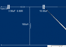
The crossover you are showing doesn't make much sense. There at least two things that reveal it can't be correct:Just took a crash course in learning how to use a circuit diagram drawing program. I'm not 100% sure of the correctness of what I drew but this is what I've got after using my multimeter to trace the connections. The 4.7uF cap is labelled as C1 in the diagram.
1) a cap in series with a two paralleled caps - in your case this is equivalent to a single cap with a capacitance of 2.93 uF. This value is not standard, but can be easily obtained paralleling 2.7 and 0.22 uF caps, and doing this way will cost far less than with the 4.7, 6.8 and 1.0 uF caps
2) the L2 inductor can't be in both woofer and tweeter circuits
Time to retrace the crossover. BTW you don't need a multimeter, only your eyes in following what is the first component after the + input, then what follows, keeping an eye when there are two components after one (a node).
As for the 4.7 uF cap, if your multimeter measures it more or less at 1 uF, then there are only two options:
1) the meter doesn't work correctly - measure something else that you know for sure, for example a never used cap
2) you removed the cap using too much heat, which partially destroyed the cap
Ralf
There is a way 🙂I have just tried to save the drawing for you, but unfortunately it removes the spaces.
Code:
resistor----| |---------| |------- +ve
|
Inductor Tweeter
|
--------------------------------- -veAllen,
Many thanks for sorting that for me.
Is the bracketed code and /code the way to do it in future?
Many thanks for sorting that for me.
Is the bracketed code and /code the way to do it in future?
You may prefer the toolbar option on the wysiwyg post editor, it gives you a box with a monospace font in which to draft it. Just click the 3 dots beside the underline button. Or, if you're like me and stay in tag mode then use the tags.
By the way, the toolbar goes away in tag mode but that's listed for a future fix.
By the way, the toolbar goes away in tag mode but that's listed for a future fix.
Ferrofluid in tweeters is a first for me. Is it replaceable or am I better off replacing the tweeters?
This is the type of ferrofluid to use, if required: https://willys-hifi.com/products/ferrofluid-refill-kit#:~:text=Ferrofluid is a cooling / damping compound used,with age, gradually reducing tweeter output to zero.
This is an example of how to replace the ferrofluid: https://speakerrepairshop.nl/en/instructions/replace-ferrofluid-in-tweeter/c-36
Great detective work there Chris.
Somebody but some design effort into that I am sure. As the use of the bypass cap in the tweeter and the inductor in the bass parallel leg are subtle additions that would improve the frequency response but add to production cost.
I do not know if Peter Comeau of Heybrook, Hi-fi World, and Mission, and IAG group fame may have been commissioned by Denon to design this crossover for them.
Hoping to hear from Limtk55 on how he is progressing with his fault finding.
A sophisticated crossover indeed, considering that a new pair of these 2009 speakers could be purchased for only £95 (RRP £110).
- Home
- Loudspeakers
- Multi-Way
- Request for help : Denon M37 speaker crossover parts replacement