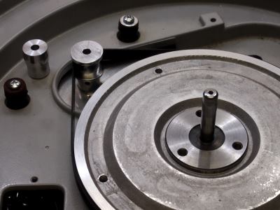
Slightly off the coil topic which is very interesting, I was wondering if someone could tell me what the triangular plate on top of the motor is there for.
Me too, I was wondering if it might be a mu-metal shield, and if so, does it make a measurable difference?
Will look for 120V neon lamps at some point per Steve above.
The shaded pole motor essentially has 4 shorted turns (each of the shading rings) which I suspect are the cause of most of the heat in the windings. Lowering winding dcr might help here, but possibly there is something of a balancing act between the winding dcr and those shading rings.. (To keep current from becoming excessive)
The existing individual windings if wired in parallel would essentially be the correct number of turns and gauge if these were to be configured as parallel connected motors. A certain minimum inductance and dcr is required to control winding losses. The combined inductance of the current tapped set up operating on 120V is identical to the inductance of the paralleled windings due to mutual inductance, the dcr should also be quite close. Interesting how that works out, Thorens could have taken either approach to building the 117V only version of the E50 - without taking one apart it is hard to know what they did. (I'd guess a series connected winding with larger gauge wire)
One other thing that is interesting to note is that copper has a pretty significant temperature coefficient so as the winding heats dcr and losses increase until thermal equilibrium is reached - this probably has a subtle effect on torque, causing it to decrease as the motor warms up due to an effective reduction of voltage across the inductive component of the winding. Possibly larger gauge wire could help this to some extent, depending on other losses in the motor.
Slightly off the coil topic which is very interesting, I was wondering if someone could tell me what the triangular plate on top of the motor is there for.<snip> -Robert
I have always understood the triangular plate provides magnetic shielding, and while I am not exactly sure what it is made of, the street says it is mu-metal. Something important to note is to avoid bending the plate, not only does that make it harder to remove and install, but if it is actually mu-metal it will badly compromise its shielding properties. Re-annealing is beyond the reach of most hobbyists given the temperature required.
Papst Aussenlaufer
I recently acquired a Papst Aussenlaufer motor and am working on a 3 phase version of the Mark Kelly drive to run it. I will start to post details of my progress once there is something to report..
So far I have built up the two boards that comprise the main part of the controller, but have yet to populate the ICs. I will do this as I proceed through the testing and set up of each pcb.
I acquired three inexpensive amplifier modules on eBay based on the LM3886TF (plastic insulated tab version) that I have to build up and test.
Target output power is 120VA total and supported voltage range will be 80 - 240V over a frequency range of roughly 50Hz - 100Hz. (The lower limit is TBD, but will probably be dependent on the transformers I selected)
I also have all of the power supply components and the chassis as well. Just have to start putting everything together, which will hopefully commence this week.
The existing individual windings if wired in parallel would essentially be the correct number of turns and gauge if these were to be configured as parallel connected motors.
Excellent point. Most USA/Euro devices such as power transformers use series/parallel configuration to change modes. I'd appear that the need to support 125-150 VAC necessitated the tapped coils style. Where in the world is 125-150 VAC used?
It would appear that in the USA one could get the advantages of Simone's coils (if there are advantages) by wiring in series.
When I lived in Italy we had a vacation place in the mountains and right down the street our neighbors had 140V/50Hz power. (1970s)
For 120V operation and only 120V operation you could wire the motor for either series or parallel windings. Volken will probably weigh in soon with a report as to whether or not there is a measurable benefit to the parallel connection, can't rule it out but it seems unlikely.
For 120V operation and only 120V operation you could wire the motor for either series or parallel windings. Volken will probably weigh in soon with a report as to whether or not there is a measurable benefit to the parallel connection, can't rule it out but it seems unlikely.
I recently acquired a Papst Aussenlaufer motor and am working on a 3 phase version of the Mark Kelly drive to run it. I will start to post details of my progress once there is something to report..
So far I have built up the two boards that comprise the main part of the controller, but have yet to populate the ICs. I will do this as I proceed through the testing and set up of each pcb.
I acquired three inexpensive amplifier modules on eBay based on the LM3886TF (plastic insulated tab version) that I have to build up and test.
Target output power is 120VA total and supported voltage range will be 80 - 240V over a frequency range of roughly 50Hz - 100Hz. (The lower limit is TBD, but will probably be dependent on the transformers I selected)
I also have all of the power supply components and the chassis as well. Just have to start putting everything together, which will hopefully commence this week.
Does anyone know the power requirements (VA) for the E50 or Papst motors?
When I lived in Italy we had a vacation place in the mountains and right down the street our neighbors had 140V/50Hz power. (1970s)
For 120V operation and only 120V operation you could wire the motor for either series or parallel windings. Volken will probably weigh in soon with a report as to whether or not there is a measurable benefit to the parallel connection, can't rule it out but it seems unlikely.
The first vibration measurements on the E50 motor with normal coil serie connection 225 volt,115 volt serie connection and 115 Volt parallel connection !
The harmonics above the 100 Hz are in the par.connection lower in amplitude but there is also a additional strong 64 Hz vibration at -55 db !
I have the impression that the motor torque is smaller but not sure must make a setup to measure this with more care , not so simple.
The measurements are for my own setup and give only a relative indication !
Next I will do the same with the motor mounted in the turntable to get a better understanding about torque,speed etc in the par.connection.

View attachment Motor Thorens E 50 TD124 Vibration 225 Volt series connected.bmp
View attachment Motor E 50 Thorens TD124 Vibration 115 volt serie connection .bmp
View attachment Motor Thorens E 50 TD124 Vibration parallel connect 115 Volt.bmp
~15VA for the E50, I don't know the VA for my Papst yet.
For the Papst 8,5VA and 7,3 Watt powerfactor 0.86 !
For the E50 motor 14,6 VA and 7,2 Watt powerfactor 0,46 !!
Volken
Papst motor vibration
For compare with the E 50 motor vibration under the same conditions the spectrum from a Papst motor with optimized phase capacitor/resistor !
Power supply mains 225 Volt .
View attachment Motor Thorens E 50 TD124 Vibration 225 Volt series connected.bmp
View attachment Motor Thorens TD124 Papst Vibration 225Volt Tuned R and C .bmp
Me too, I was wondering if it might be a mu-metal shield, and if so, does it make a measurable difference?
Yes it does see measurement with magneticfield meter
Volken


This is the lovely and hand-built Mørch GS6a, another Idler-wheel drive turntable
It also uses a Papst aussenläufer motor, but this is somewhat smaller than the one used for replace the E50 motor in the Thorens (it is identical to the one used in the Michell/Transrotor Hydraulic/Electronic Reference).
The reason I am posting these pictures is Hans Henrik Mørch's unusual meted of balancing the motor: it was individually tuned by means of the RC circuit, but in addition he individually balanced every motor by adding little pieces of tape to the rotor. As you see on this picture, there are no bits of tape on one side of this motor:
Perhaps this is a technique that should be explored some more for the Papst motor in the TD124?
ARGH: I cannot figure out how to insert pictures, so here are URLs to them:
https://www.flickr.com/photos/8291725@N02/14135459702/
https://www.flickr.com/photos/8291725@N02/14135469602/
https://www.flickr.com/photos/8291725@N02/14158486423/
An externally hosted image should be here but it was not working when we last tested it.
It also uses a Papst aussenläufer motor, but this is somewhat smaller than the one used for replace the E50 motor in the Thorens (it is identical to the one used in the Michell/Transrotor Hydraulic/Electronic Reference).
An externally hosted image should be here but it was not working when we last tested it.
The reason I am posting these pictures is Hans Henrik Mørch's unusual meted of balancing the motor: it was individually tuned by means of the RC circuit, but in addition he individually balanced every motor by adding little pieces of tape to the rotor. As you see on this picture, there are no bits of tape on one side of this motor:
An externally hosted image should be here but it was not working when we last tested it.
Perhaps this is a technique that should be explored some more for the Papst motor in the TD124?
ARGH: I cannot figure out how to insert pictures, so here are URLs to them:
https://www.flickr.com/photos/8291725@N02/14135459702/
https://www.flickr.com/photos/8291725@N02/14135469602/
https://www.flickr.com/photos/8291725@N02/14158486423/
Interresting do you have a number from the motor on the picture its difficult do see, there are four wires for motor connection correct ?
In the motor powersupply I see two outputtransformers ?but no drivers and the crystal from the oscillator .
The balancing from the outer rotor from the Papst is important I shall try to fix tape on it and see what it does on the motor frequence from 24 Hz . At the E 50 motor a small unbalance translates in a higher vibration amplitude.
I have the Delphon GS5 turntable same designer as Morch ? It use no Papst motor.
Volken
Hi Volken,
I shall post the Motor number tomorrow.
When Delphon went bankrupt in the mid-sixties, Mørch bought their tools (but not the name) and first made the GS6 (the same as the GS5, but with a 30cm [12"] platter instead of the 25 cm [10"] platter Delphon had used). The GS6a is basically a GS5 with 12" platter and the Papst aussenläufer (but massively refined). Mørch later made a suspended subchassis version, the subchassis being cast bronze. I sold my Linn Sondek to buy that one, it was that good! Unfortunately, the one I have now is non-suspended. One day, however.....
Last edited:
TE=his047;3920125]This is the lovely and hand-built Mørch GS6a, another Idler-wheel drive turntable
The reason I am posting these pictures is Hans Henrik Mørch's unusual meted of balancing the motor: it was individually tuned by means of the RC circuit, but in addition he individually balanced every motor by adding little pieces of tape to the rotor. As you see on this picture, there are no bits of tape on one side of this motor:
Perhaps this is a technique that should be explored some more for the Papst motor in the TD124?
As you see on the picture there is a piece off tape on the rotor the first narrow spectrum is from the rotor asis the second with the tape.
own motor freq.goes -7 db down , second and third harmonic goes 10-11db up !
This shows how important balancing is on turning objects !
Volken

View attachment Motor Papst TD124 Vibration narrow balance asis.bmp
View attachment Motor Papst Thorens TD124 Vibration narrow Rotor unbalance .bmp
The reason I am posting these pictures is Hans Henrik Mørch's unusual meted of balancing the motor: it was individually tuned by means of the RC circuit, but in addition he individually balanced every motor by adding little pieces of tape to the rotor. As you see on this picture, there are no bits of tape on one side of this motor:
Perhaps this is a technique that should be explored some more for the Papst motor in the TD124?
As you see on the picture there is a piece off tape on the rotor the first narrow spectrum is from the rotor asis the second with the tape.
own motor freq.goes -7 db down , second and third harmonic goes 10-11db up !
This shows how important balancing is on turning objects !
Volken
View attachment Motor Papst TD124 Vibration narrow balance asis.bmp
View attachment Motor Papst Thorens TD124 Vibration narrow Rotor unbalance .bmp
I finished my experimental belt drive and it's working. 🙂
I used a Hurst permanant magnet syncronous AC motor that I purchased from the Hurst website. Even though it was made to order it they delivered in less than 2 weeks. I chose a 24VAC model because it seems it'd be easier to build a varable frequency power supply if I choose, and I figure it makes sense to run it from a remote transformer isolated low voltage power supply. The transformer core and enclosure can be line grounded for safety while the TT can be system grounded.
When first powered it up all seemed well. However when I put the cast iron platter on It ran for a turn or so then the belt slipped off. I found that without the platter the belt stayed on the pulleys crowns but when I loaded the spindle with my fingers the belt rode off the motor pulley. I made a new motor pulley with shoulders. they successfully keep the belt in place during heavy loads. They don't interfere with normal operation. The belt returns to the crown once the table reaches speed, in this case in one revolution.
Then I checked the speed with the platter strobe markings. I was severely disappointed. It was running way slow. I removed the platter, put a strobe disc on the big pulley and found it running fast. I couldn't believe my motor did not have the guts to drive the TT. Before giving up I changed the transformer to a Stancor RT - 204. The RT series has a special two winding multy tapped primary that can be wired in ten configurations to provide different output voltages. I set it for 28V. Now it ran at the same speed with and without the platter. I reduced the voltage to 25V and it still ran fine. The problem was not the voltage but rather the low VA rating of the first transformer. Greatly relieved I spent the rest of the evening moving the motor pulley back and forth from the TT to my milling machine shaving a little off each time then checking the speed. After a dozen or so iterations the speed is close. It takes over a minute for the dot to travel from one side of the viewing window to the other. I'm going to run it for a while before I make the final adjustment. I don't want to over shoot. Then I'd have to shave the big pulley which would be a PITA to remount on the mill.
I'd calculated that with a 300 RPM motor the big pulley should be 9 times the smaller. The big one is 135mm so the little one should be 15mm. Curiously, the small one is now 14.48mm and it's still slightly fast.
Both pulleys use the same surface of the belt so thickness shouldn't be an issue. Maybe the crowing on the big pulley has the effect of reducing the effective diameter. I donno.
- Home
- Source & Line
- Analogue Source
- Restoring and Improving A Thorens TD-124 MKII