Hello, I'm new here. And new to circuitry. So bear with me please, I don't have really any experience with circuits other than electrical (residential/commercial) circuits.
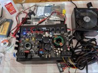
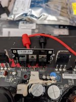
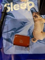
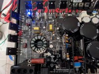
I have a Rockford Fosgate P1000-1bd that I got cheap (too good to be true). Cosmetically good shape. I opened it up and found the output capacitor with a broken leg but everything else looked fine. The cap also had burn marks on the leg of it as if it has arc'd. So I replaced it with a Panasonic ECQ-E1106JF (below is a picture of the old one and then new one installed)
The amp powers up but does not have any sound or output when feeding it a signal from my phone through the RCA. No DC on speaker terminals.
I found that Q2000 transistor seemed to read very odd, it had - 19v, -. 741, - 7xx. I replaced it, now it's reading - 22v, - 7.01v, - 7.11v.
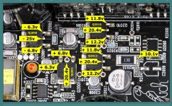
When I measure the rectifiers (CR1004 & CR1005) from left pin to left pin I get -83.7mV DC, center to center I get 55v DC, right to right pins I get -84.7mV DC. Seems very odd.. The rest of these transistors read accordingly to this picture attached with voltages that I found in another thread.
The 75344G fets voltages all have:
6.68-6.7v DC gate to drain
12.06v DC source to drain
5.44-5.45v DC gate to source
Not exactly sure what I'm supposed to see on these?
All the fets to left of the rectifiers (IRFP3415) read in the mV range jumping around on all their pins..
Nothing is getting hot on the board either.
My test bench consists of a computer psu that puts out 12.08v
Unfortunately I do not have an oscope..
Looking for suggestions on what to check next.


That's a 13 ohm resistor. 1 and 3 are the significant digits, 0 is the multiplier.
For example:
130 = 13
131 = 130
132 = 1300
133 = 13000
Edit: I'd wait for someone familiar with this board to chime in before you start throwing parts at it. I'd love to help but am still learning myself.
For example:
130 = 13
131 = 130
132 = 1300
133 = 13000
Edit: I'd wait for someone familiar with this board to chime in before you start throwing parts at it. I'd love to help but am still learning myself.
Last edited:
Edit* it reads 10.5v and ohms out to 13.3 so seems to be in spec. Not sure where I got 1.5v from before lol
Most importantly...
To upload photos click the following:
Go Advanced
Manage Attachments
Browse
Upload
Repeat as necessary
Preview post to see how the post will look.
Click Submit Reply to send it to the forum.
~~~~~~~~~~~~
The burning on the cap was due to the intermittent contact and arcing.
When you post the voltage on transistors, go left to right. For the regulator transistors, the greatest voltage will be on the center legs (middle number).
For the rectifiers, center to center is what's important.
The PS FET voltages are OK. If it's making rail voltage, everything in the main part of the power supply is likely OK.
Have you operated all pots and switches through their entire range while listening for audio to see if it every played through (even just for an instant)?
Some amplifiers won't function properly with a signal source that doesn't have a grounded shield (like a cell phone).
~~~~~~~~~~~~
Please (and this applies to anyone who needs repair help) use your sig line to list all equipment you have, editing it as equipment changes. Include the model numbers.
Top of page, menu USER CP >> EDIT SIGNATURE
Oscilloscope (yes or no)
Multimeter(s)
Type of signal source (grounded RCA shields preferred).
Soldering iron
Desoldering pump
Power supply
2 ohm current limiting resistor (hollow cylindrical ceramic 100w preferred)
Left to right
Q2000
-7.01vdc, - 23.1vdc, - 6.50vdc
Q2001
6.75vdc, 21.8vdc, 6.15vdc
Q2012
11.76vdc, 21.8vdc, 11.49vdc
Q2010
11.77vdc, 21.8vdc, 11.51vdc
R2035
11.16vdc at the top and 1.19vdc at the bottom (closer to speaker terminals)
Also the amp is drawing 0.83A at idle. Spikes to 0.98A at initial startup.
The remote wire pull 0.15A Idk if that matters but figured I'd post it anyways.
I connected my amp to my AV home receivers sub out and adjust dials as I played music through and could not get any sound out of a tester woofer connected to the outputs of the amp.
Last edited:
It appears that there is a problem with R2035.
Remove it, check it. If it's within tolerance solder it back into the circuit and re-check the voltage.
Remove it, check it. If it's within tolerance solder it back into the circuit and re-check the voltage.
So I took that resistor out, noticed that one side came off as soon as I put the iron to it. . It ohmed out to 13.3, put it back in and now I have sound!! Thank you so much Perry!
Oh I wanted to say that, the resistor ohmed out to the same installed and has 9.58vdc. I'm guessing that's within spec?
- Home
- General Interest
- Car Audio
- Rockford P1000-1BD No Output
