I don't know which kind of pine it is. It's made in China or Russia, looks like this, more or less:
An externally hosted image should be here but it was not working when we last tested it.
I didn't know about that store.
No chance they'll get to the east coast, I presume.
I should be glad we at least have half a BnQ here! 🙂
No chance they'll get to the east coast, I presume.
I should be glad we at least have half a BnQ here! 🙂
I don't know which kind of pine it is. It's made in China or Russia, looks like this, more or less:
Ok, not sure how the glued together pieces will change things or exactly what kind of pine that is, so I just went with a decent looking white pine. Model was fixed at the back edge to allow side wall bending. I moved the braces and changed grain direction to maximize first mode frequency. Results are interesting, not quite what I expected which is why it's good to run simulations like this. Final grain directions and brace positions shown here:
First mode was at 247 Hz. The top-down view shows the bending of the side wall, indicating the transfer of movement through the braces into the side wall. In this mode the panels are moving in phase.
The second mode is the panels moving 180° out of phase, so not surprising the mode is only slightly higher at 256 Hz. These first two modes show why the brace XRK used on the 0.4x Karlsonator is so effective.
Lastly, the panels are moving with a higher order mode at 405 Hz. A good jump, and hopefully outside of any frequencies you plan on playing through this speaker.
I hope that helps with your build! I look forward to hearing about your results.
Attachments


MJ,
Great work and beautifully presented. This is very helpful. I wish I had the FEA option on my SW's.
Great work and beautifully presented. This is very helpful. I wish I had the FEA option on my SW's.
MJ,
Great work and beautifully presented. This is very helpful. I wish I had the FEA option on my SW's.
Thank you!
Yeah, it's nice. It's so fast to simulate this stuff. The package is pricey, I'm lucky it's needed for work.
Thanks a lot for the time the effort on this.
I'm thinking, in reality, things will probably turn more complex as I will add more and more stuff on it.
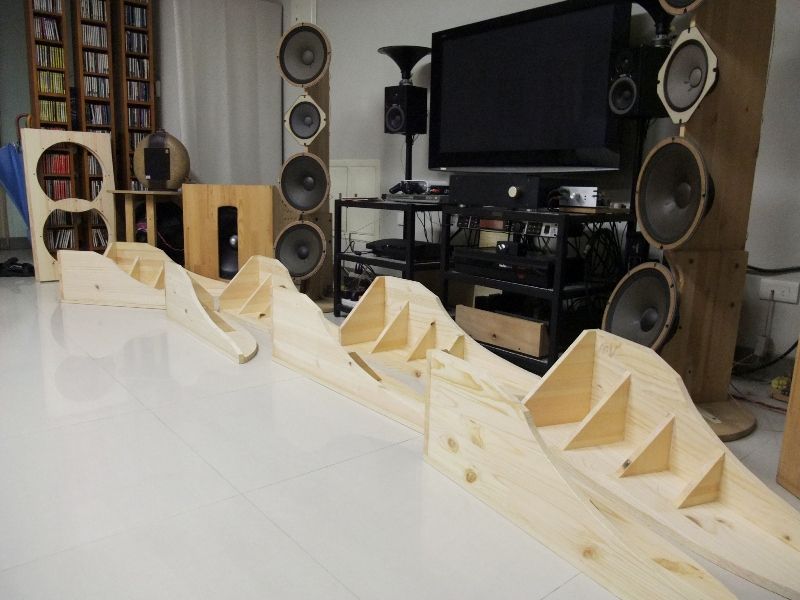
For a start, the side walls are actually double thickness and secured by screws. (their grains are vertical) And I would probably spread those triangles more evenly, and add more, to be the supporting ribs of the following PU foam block (if I really go that far).
I'm also thinking of different mounting methods for the triangles -- rigid and flexible alternatively....
The building progress has stopped for more than 2 weeks. See what I can do in the following weekend.
I'm thinking, in reality, things will probably turn more complex as I will add more and more stuff on it.
For a start, the side walls are actually double thickness and secured by screws. (their grains are vertical) And I would probably spread those triangles more evenly, and add more, to be the supporting ribs of the following PU foam block (if I really go that far).
I'm also thinking of different mounting methods for the triangles -- rigid and flexible alternatively....
The building progress has stopped for more than 2 weeks. See what I can do in the following weekend.
Thanks a lot for the time the effort on this.
I'm thinking, in reality, things will probably turn more complex as I will add more and more stuff on it.
For a start, the side walls are actually double thickness and secured by screws. (their grains are vertical) And I would probably spread those triangles more evenly, and add more, to be the supporting ribs of the following PU foam block (if I really go that far).
I'm also thinking of different mounting methods for the triangles -- rigid and flexible alternatively....
The building progress has stopped for more than 2 weeks. See what I can do in the following weekend.
Simulations like what I did are great for getting an idea of the behavior, but it's still just a simulation. If the one thing you learn from my work is to add more ribs, that's great. I will not take any offense if you're final design looks nothing like my sim. Spreading the ribs will drive higher modes even higher. I would only caution you not to add mass without adding stiffness toward the middle of the aperture wings, that would drive the first mode down in frequency. It looks like a great concept, and most minor modifications only moved the frequency a few Hz.
Let me know if you'd like me to simulate any alternate configurations.
Good luck with the build.
Thank you for your simulations MuddJester.
If you have the time I wonder what would be the effect of having a single rib down each wing instead of 4 ribs across.
If you have the time I wonder what would be the effect of having a single rib down each wing instead of 4 ribs across.
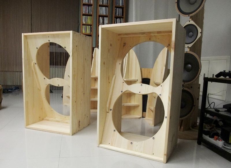
Ok, mine are pretty much done.
Some photos:
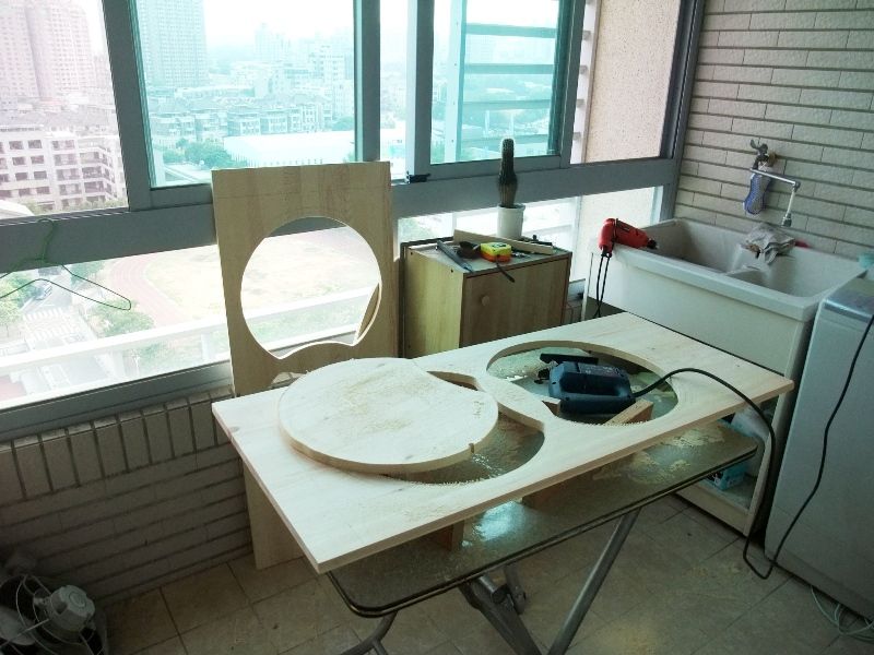
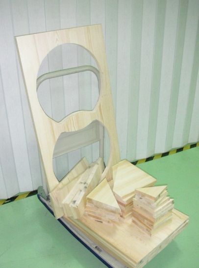
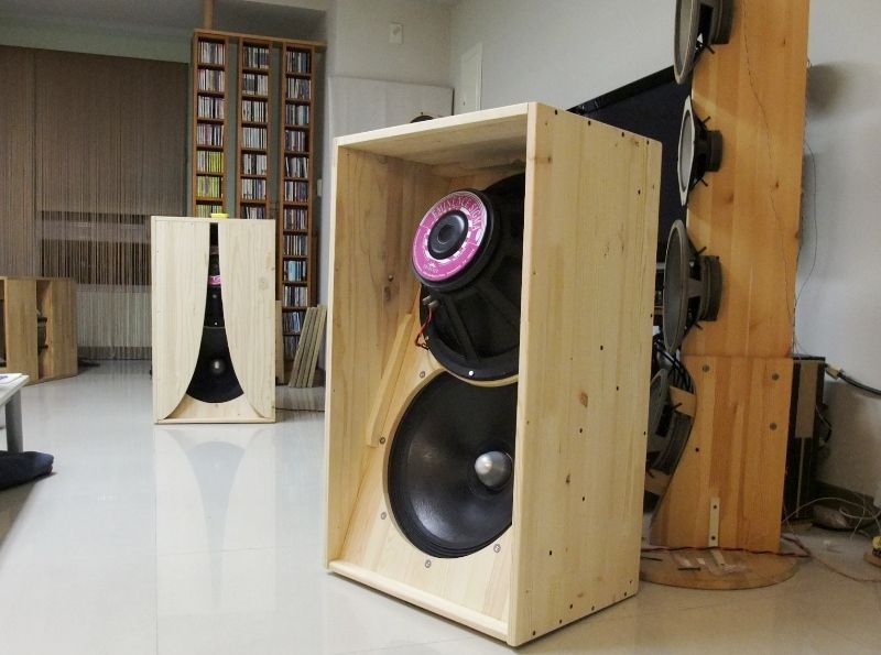
BTW, the idea of overlapped woofers is stolen from here:
truefi: June 2014
(scroll down, the last picture at the bottom of that page)
Some photos:
BTW, the idea of overlapped woofers is stolen from here:
truefi: June 2014
(scroll down, the last picture at the bottom of that page)
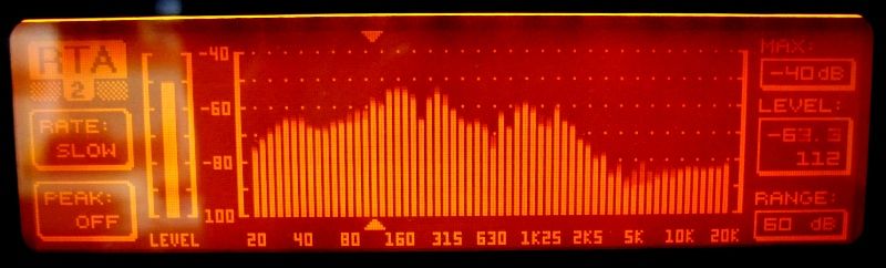
No proper measurement, only RTA on DEQ2496:
This was taken from 1-ch, ground plane at 1m away. I managed to place the Kalson in the middle of the room, as far to other objects as I can:
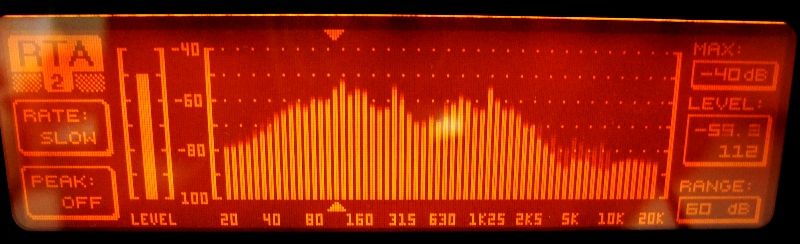
And this was taken at the listening position (about 3m away) with both channel playing at their normal positions (away from the front wall by 60 cm or so):
They're driven by a modded LM3886 chip amp with 10 Ohm output impedance.
It's already too late to play them loud last night when I finally got all things done. The FR is not pretty, but it sounds smooth enough to my ears in the quiet volume. As expected, it's not the kind of 'accurate' sound with ruler flat FR, but somewhat in the warm and rich side.
Full assessment will have to wait until I mod the PLLXO in my pre-amp and find a proper HF unit for the upper half of spectrum.
This was taken from 1-ch, ground plane at 1m away. I managed to place the Kalson in the middle of the room, as far to other objects as I can:
And this was taken at the listening position (about 3m away) with both channel playing at their normal positions (away from the front wall by 60 cm or so):
They're driven by a modded LM3886 chip amp with 10 Ohm output impedance.
It's already too late to play them loud last night when I finally got all things done. The FR is not pretty, but it sounds smooth enough to my ears in the quiet volume. As expected, it's not the kind of 'accurate' sound with ruler flat FR, but somewhat in the warm and rich side.
Full assessment will have to wait until I mod the PLLXO in my pre-amp and find a proper HF unit for the upper half of spectrum.
Last edited:
Nice balcony conversion into a workroom! At least, it's covered and you still can work when it's rainy. I'm open to the outdoors on my balcony, so can only work on rainless days! Which are few lately!
There are some serious toys in that listening room, and those behemoth kazbas look mighty impressive!
Even with that much space, you'll soon run out of real estate in that room for all your toys! 😉
Great job!
Have fun tweaking now!
Get DRCDesigner and try that. I think it would work really well with those kazbas.
WOW!!! Those things are HUGE!
Very nice execution and excellent details of overlapped drivers and ribs for the wings.
The LF extension is pretty good I think for an OB dipole. The HF extension is much better than I thought. You are clearly reaching above 1kHz and that is a great feat.
Regarding the non flat frequency response - that is o be expected of K slot designs with having a 10dB dip in the mid bass and here I see a 240Hz sharp notch and a larger 640Hz one that is different depending on if it's played in middle of room vs near walls.
The foam inserts between the ribs and on back side of K aperture may smooth those dips out.
The 640Hz dip corresponds to a 10.5in distance from cone to surface that is causing the back reflection cancelation. This may be cone to about mid distance of back of K aperture. Add thick felt to back side of K aperture near mid point and see if it doesn't smooth things out. Or add shaped foam plug to achieve same thing and even greater HF extension. I would try felt first. Also try adding stuffing around backside of drivers around where narrow K aperture is.
Good luck and thanks for trying this out on a huge scale!
Last edited:
from my sense of aesthetics, they look great 😀 - what happens if you lower the source Z? - would they be overdamped? - is there enough sense of "power" compared to your previous slot loaded sub?
Thanks for the kind words and tips. Will do.
And, the woodwork is actually lousy. All I can do is butt joint with screws and glue. There're countless faults hidden by the low-res photos. (also, I didn't post them all)
Braced wings might be a bad idea, I think. It's not worth the effort and brings trouble. In this case, there're 3 sides in each wing, but they are not perpendicular in some. (my fault, of course) I found this when doing the assembly, while it's too late (and I was too tired) to fix. So, they don't fit in well enough. Eventually I can just throw them together recklessly. Horrible gaps everywhere. It's 3mm off in the worst case.
There're so many things to do next.
And, don't thank me. Thank you. This has been in my to-do list for quite a while. It's you stirring up the motivation.
------
@ perceval, I read your DRC thread. I don't understand most of it, but it seems very high potential.
I will try it. I mean, I'll put it in the (long) to-do list, hehe...
Hi freddi,
Thanks for your kind words. The amp with high output impedance is already there for driving these low Q woofers in previous OB. Now it's still dipole, so I suppose it's good to compensate the dipole loss somewhat.
From the previous experience, such high impedance would merge with Re and give a system Q of 1.1 (the woofer itself is 0.3 or so). Several dB of boost around fs is realized by this alone. It's also good to spread the amount of required EQ among various stages. And it sounds good to me.
As to the sound quality in more aspects and other details, we have to wait a little longer to find out. They were just hooked up last night. 🙂
that was a cool way to raise system Q - - in a way, the mids probably have the horizontal dispersion of a 6 inch speaker. I had my excellent cabinet builder make two 0.65 scale K15's to try 10" or 8" - here's a 10"

Last edited:
CLS,
You may be going this way already, but my recent experience with the FAST using the RS225 and 10F has shown that a first order XO allows one to achieve a transient perfect step response. With the very wide bandwidth of your Kazba, I think you could use a 1st order Butterworth. Especially since you have a dipole sub - having a triangle step response once integrated with your tops may produce the most amazing visceral impact for transients and percussion.
You may be going this way already, but my recent experience with the FAST using the RS225 and 10F has shown that a first order XO allows one to achieve a transient perfect step response. With the very wide bandwidth of your Kazba, I think you could use a 1st order Butterworth. Especially since you have a dipole sub - having a triangle step response once integrated with your tops may produce the most amazing visceral impact for transients and percussion.
- Home
- Loudspeakers
- Full Range
- Rockin' the KaZba Dipole (K aperture Z-baffle Dipole)