Rohde & Schwarz UPD: #1 Troubleshoot then Restore to Glory
I just opened up my UPD and thought I would get it up and running. I don't know whether to keep this in the UPD thread or start a new one.
Anyone that has completed the Cap replacement on which are the most likely
candidates?
Mother Board?
Power Supply board?
I need to post this so I can find it and read it again while posting my other questions.
ELKO Caps, Brand is elko yes?
It's hard to see in there, and dusty.
I'll blow it out soon.
Yes, I have the top and bottom off the unit.
There is additional shielding (sheet metal) that
needs to be removed.
Are we talking the PSU board or Power Supply?
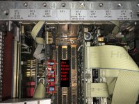
Power supply being on the BIG heat sink with the
two shielded transformers. I haven't testing anything,
just trying to only remove the screws and parts needed
then ID the proper parts for replacing.
Goal is to get it working before doing hard drive and
DOS upgrades.
I'll post what pics I have. My UPD is optioned out except for
the AES-EBU Spidf and the 2nd Digital plug in with COM 2
and word port.
Any one who's refurbed this have a BOM or Digikey order etc?
This is the start of these two threads with the same name.
I just opened up my UPD and thought I would get it up and running. I don't know whether to keep this in the UPD thread or start a new one.
Anyone that has completed the Cap replacement on which are the most likely
candidates?
Mother Board?
Power Supply board?
I need to post this so I can find it and read it again while posting my other questions.
ELKO Caps, Brand is elko yes?
It's hard to see in there, and dusty.
I'll blow it out soon.
Yes, I have the top and bottom off the unit.
There is additional shielding (sheet metal) that
needs to be removed.
Are we talking the PSU board or Power Supply?
Power supply being on the BIG heat sink with the
two shielded transformers. I haven't testing anything,
just trying to only remove the screws and parts needed
then ID the proper parts for replacing.
Goal is to get it working before doing hard drive and
DOS upgrades.
I'll post what pics I have. My UPD is optioned out except for
the AES-EBU Spidf and the 2nd Digital plug in with COM 2
and word port.
Any one who's refurbed this have a BOM or Digikey order etc?
Last edited:
So here are some of this pics, and I've got more questions.
Does everything need to be removed to replace the mother board
capacitors that fail?
And, while I'm in here, should I pull out the Analog analyzers and
look for caps in there also? Are ELKOs in there too?
I'll post a a better motherboard pic so the plugin boards
align up properly.
Cheers,
Does everything need to be removed to replace the mother board
capacitors that fail?
And, while I'm in here, should I pull out the Analog analyzers and
look for caps in there also? Are ELKOs in there too?
I'll post a a better motherboard pic so the plugin boards
align up properly.
Cheers,
Attachments


Update with the following:
Leaky Green Battery, Bat 1 = 1.124v. It says 035 on it.
Looks to be 3 stacked batteries. Any one know type?
Big blue battery on Digital Generator board (V12) dated 10/95 = 3.702V.
Then some pics of both digital boards front and back so everyone
has a reference as to what they look like.
V12 is the Digital Generator board.
V11 is the Digital Analyzer board.
Note: They both have fixes on the rear of the boards
that didn't make it into the final board design.
Caution:
When attempting to remove the Heat Sink Power Supply
I almost severed the on off cable and switch. Then one
of the Xfrmr can lids almost broke off. Nothing a little
English, errr Deutsch won't fix and lid is back on without an
issue.
On the mother board I only see one electrolytic cap.
Is that they only one?
Is that also an issue?
Cheers,
Attachments
-
 01.06.A11 Dig Anal Rear.jpg367.6 KB · Views: 130
 -
 01.06.All Dig Anal Front.jpg401.4 KB · Views: 132
 -
 01.05.A12 Dig Gen Back.jpg374.8 KB · Views: 126
 -
 01.05.A12 Dig Gen Front.jpg342.4 KB · Views: 139
 -
 01.01.02 Mutha Aligned.jpg411.9 KB · Views: 128
 -
 01.01 Mutha Bat1 Leak..jpg129.7 KB · Views: 219
 -
 01.01 Mutha Board Cap.jpg362 KB · Views: 127
In the mean time there is nothing else to do.
We are getting snowed in and blizzard hits
tomorrow night.
For those who don't understand Texas drivers,
they tend to accelerate on Iced over bridges.
When they try to stop, they used to skid out of
control, but now they have a fix for that,
it's called anti-lock brakes,
so there is no stopping
the cars now where
before you could
skid to a stop with
the build up of snow
and ice on the front of
the tires.
But that doesn't happen with
god ol' anti lock brakes.
At least some engineers
figured it out and put a
no anti-lock brake button
on some of the cars so you
don't drive through busy intersections.
Enjoy.
Cheers,
Last edited:
Thank you Rohde & Schwarz
for removing the Maintenance sections
from all your UPD manuals.
So you aren't supporting the products any longer
and in typical European fashion you aren't going
to help the regular folks keep these things working.
It's just an Effing Schweinerei.
Prost mit dem Mittefinger Hinein.
The more I work with this stuff
the more I appreciate the standards
set by our good friends at Hewlett Packard.
Not only did they make good stuff but they
took great pains so that Techs and Hobbyists
using their gear to keep them running.
Same thing with Tektronix and others too.
Last edited:
SyncTronX,
Your motherboard must be the same one as mine.
The board is fixed by cards on ISA bus and a retainer on the edge of the board of the CPU side. I forgot the screw is fastened from which side but removing the screw and slide it, you can pull the motherboard from the left side of the instrument, opening of the chassis. I could not just pull the board upside why there is a PSU module for the motherboard (which you wrote power distribution hub).
Then, the leaked battery. This is a typical symptom on vintage computers those days. You must remove it and clean the alkaline around it. I just used water and alcohol, but some vintage computer fans use a kind of vinegar.
The electrolyte corrodes copper traces and some of them were lost. I soldered jumper wires to repair. Yours also looks like have darkish corroded traces. One of the traces will be the supply to the ISA bus, so it may be the cause of the malfunction.
Next, the battery replacement. Actually, you don't need to replace the green one. UPD has another battery, half AA size non-rechargeable Li-battery, mounted on chassis and electrically connected through wires. Mine has been low voltage so I replaced it by AA size Li-battery (because I could get it cheap) but a typical coin cell may be OK.
Last edited:
Thanks Sinja,
I'll remove the mother board which I think has one screw in the center
removed from inside the UPD. I'll do that later on
then removed that 035 battery from the board and clean it up.
On post #94, pic 3, on the left edge of the board is Big Blue = 3.702V.
I'm guessing that keeps the Digital Analizer memory or something.
Where is the other battery you mentioned in the chassis?
I've looked but have not found it, yet, the one that's velcro attached?
So, are those the ELKOs that go bad in these units that I've highlighted?
Or were ELKOs brown blob cylinders and not the light blue caps?
Thanks for your suggestions. I'll clean off that battery area,
after I remove that mother board thanks for explaining the procedure.
I've removed the two large boards I'll have to look in the corner where
it looks like two additional boards are. Checked post #93, pic 1.
Three boards are there:
Slot 1 A17, IEC-BUS Option B4
Slot 2 A14, MULTI - I/O
Slot 3 A13, VGA-CONTR
Cheers,
Last edited:
Sinja,
I found the chassis battery, on vertical mount, and it feed the mutha board, right
where the SMPS connections are also.
I assume it's alright to removed the connections as the important stuff should be
on the hard drive. Maybe the batterys only save the current configuration of the
boards.
I found a mess on SLOT 3. I think R&S taped up two large pads on the reverse that
weren't being used, along with a pair of diodes. The sticky stuff ran down the
board into the slot. It also migrated to SLOT 2 board and infected it,
the red 4 pin switch and some other stuff.
I can't get it off my hands at the moment. Will try various solvents later on.
Film at 11.
Cheers,
Post Script -- QUESTION it occured to me that the "ELKO" isn't a brand name,
rather it is jargon for "electrolytic capacitor"? Holy smokes folks, it would be nice
if we'd include the definition before or after first use in a thread.
Electrolytic Capacitor ([ELKO, common use in the EU], [Lytic,use by some
in the Americas]). There is a lot of these Lytics populating the various board,
and The analog power supply board along with the SMPS in the center.
QUESTION 2 Looking at the Schaffner EMI filter it's looks to be fine,
how ever is it worthwile to replace the working until now or wait until
later if and when it burns up?
OR
Follow the "don't fix it if it ain't broke."
Cheers,
Last edited:
- Home
- Design & Build
- Equipment & Tools
- Rohde & Schwarz UPD: Troubleshoot then Restore to Glory