Hi, long time no see!
recently i got from a friend a good old amplifier from rockford fosgate. Its the P8004 4 channel amplifier, which stated in its name.
Amplifier was working ok but suddendly stopped working from one of their 4 channels. Short yellow led lit, so we removed from the car and bench test it.
None of the 3 40 amp fuses blew, and the amp still worked on the 3 remaining channels, good clear sound, no distortion.
Front left channel blew (a low pitch tone), so i discovered my friend wired in paralell an infinity kappa speaker , 2 ohm, with another focal 6 inch speaker, 4 ohm, so, yikes! Thats 1.3 ohm so way low from the 2 ohm stereo per channel spec!
Well, i went to test all the transistors, so the first row of two 28n15 were bridged to ground, got 0 ohms each way. The another ones (fqa36p15) werent shorted, and tested all the transistor, and they at least were not shorted.
So i ordered a pair of 28n15, installed them on the MEHSA strip (god, that was not easy!), and discovered two of the small condensors on C117 and C118 blew in half. Weird! I said, maybe i damaged them without noticing.
I searched on the net, and found schematic of the amp, so , if my memory serves me right, the replacement part i need its a “ 104- condensador de 0.1 microfaradios, 50 Volts, 5% tolerancia”. That being said, i jumped to my nearest electronic parts supply, but found a part with +80% -20% tolerance range! So i am stumped if i can use this part, or if i need the exact replacement.
i am attaching some pics of the amp board, pics of the schematic from rockford, and pics of the replacement part i have readily avaible.
Thanks in advance, sorry , english its not my first languague and electronics are not my field of work (i am a fireman), i hope i have been clear with my explanation.
Attachments
-
 E8E77574-A3B2-4DCF-903F-70BCF7B6D2DC.jpeg87.7 KB · Views: 165
 -
 F57C9D56-95E0-4935-83F1-4847A41EDD21.jpeg593.8 KB · Views: 188
 -
 F7F2C625-9909-4EE8-B373-04A81304EC98.jpeg626.7 KB · Views: 163
 -
 ED255E92-6034-4E7C-BA09-A8AAF7CD6F9D.jpeg559.2 KB · Views: 190
 -
 D57747DD-862C-4E92-9BC1-A2FE7B721E68.jpeg76.7 KB · Views: 162
 -
 D0936369-04A7-49E8-B369-6C74D266C742.jpeg66.4 KB · Views: 154
Did you re-check the replacement output transistors after they were installed onto the MEHSA insulator?
It's not difficult if you heat the insulator from the back with a small butane (not propane) torch. Some people use hot air but I prefer the torch.
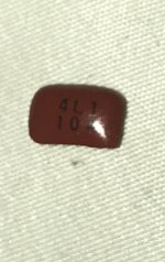
The 'photo' of the yellow caps are not of a 0.1uf capacitor. The text is OK.
Before applying power, set the bias pot fully counter-clockwise for that channel.
I'd recommend going back to the film/Mylar capacitor but the ceramic you have may work perfectly well.
It's not difficult if you heat the insulator from the back with a small butane (not propane) torch. Some people use hot air but I prefer the torch.
The 'photo' of the yellow caps are not of a 0.1uf capacitor. The text is OK.
Before applying power, set the bias pot fully counter-clockwise for that channel.
I'd recommend going back to the film/Mylar capacitor but the ceramic you have may work perfectly well.
Hi Mr Babin! Glad to see you around. I recall you helped me to fix my kx.5002 (like ten years ago)
i have not powered the unit yet, but tested both transistors after installing and these reads about the same when these were unmounted (it did not read shorted like the previous ones)
I will counterclokwise bias for channel 1 prior powering unit.
Checked with local supplier and had another capacitors, which looked like the original ones. Here the specs and pics (i think the pic of the capacitor its a generic one, but the specs are real)
Will this one make a better replacement?
Attachments


I don't know if it's better than the yellow capacitor.
The yellow ceramic capacitor should be good enough for testing.
Without testing the actual substitute capacitors, no one may be able to tell you whether the substitute will work under every condition.
Why not order the identical capacitor?
The yellow ceramic capacitor should be good enough for testing.
Without testing the actual substitute capacitors, no one may be able to tell you whether the substitute will work under every condition.
Why not order the identical capacitor?
Hi Mr Babin! I went to my local supplier but he said he would not have the exact replacement until a few weeks.
i bought “capacitor ceramico 104” (the round one 0.1u farad and installed both in the amp. Reset bias potentiometer all counter clockwise like advised.
Triple checked everything, clear board and soldering points with isopropyl alcohol, reinstalled mehsa strip, and connected to computer PSU (it only gets 12.5 volts but works)
Short light led still on, but now channel 1 works well, and bridged with channel 2 works well too. I had clear sound, but i must say, it sound clearer and a little but more “louder” than channels 3 and 4, even bridged , pairs 1-2 are louder than 3-4.
I never reached more than half gain (i know computer psu wont give 13.8 steady volts)
At all times the replacement parts didnt get hot or hotter than the other older transistors, during all the hours of testing at 4 ohms.
Have been reading and watching videos how to set the bias on an sound amplifier but many of them requires an O-Scope, which i dont have. Is there another way to accomplish this?
Thanks in advance. I am attaching a picture of the installed caps.
Attachments

With a computer power supply, you don't have an amp meter (my preferred way of setting the bias). The Rockford spec is 2mv across each 0.1 ohm source resistor. That's too high, in my opinion. I'd set the bias to about 1mv. If, for this amp, 2mv doesn't result in high idle current or excessive heating at idle, you can use it.
All FETs must be tightly clamped to the heatsink while adjusting the bias.
All FETs must be tightly clamped to the heatsink while adjusting the bias.
- Home
- General Interest
- Car Audio
- Rokford Fosgate P8004 FQA28N15 and 104 Condensors