Hi Everyone,
I'm in the process of knocking out holes in a chassis for some small Chinese analog panel meters.
Unfortunately every drawing online seems to be conflicting. I must be getting old but these drawings
make zero sense to me. Does anyone have a physical meter they wouldn't mind measuring for me?
Just need the usual...
Ron
I'm in the process of knocking out holes in a chassis for some small Chinese analog panel meters.
Unfortunately every drawing online seems to be conflicting. I must be getting old but these drawings
make zero sense to me. Does anyone have a physical meter they wouldn't mind measuring for me?
Just need the usual...
- Hole Size needed to slide the thing in from the front. I won't be rear mounting with the face protruding through the front panel
- Physical edge to edge dimensions
- Mounting hole to mounting hole dimension
Ron
Do you have a link to the meter?
I would wait to make all the holes until you have the meters in hand.
You never know.
I would wait to make all the holes until you have the meters in hand.
You never know.
This is just one of a zillion.. looking online produces 3 or 4 variations of the drawings. You're right though. I should just wait but its a slow journey 🙂Do you have a link to the meter?
https://www.aliexpress.com/item/100...tnKnxUbI&utparam-url=scene:search|query_from:
That does not look like a standard classic meter layout.
And it's metric, so I would wait until they arrive to work the sheet metal.
I also wait for all the parts before laying out pcbs.
And it's metric, so I would wait until they arrive to work the sheet metal.
I also wait for all the parts before laying out pcbs.
Metric is good and it is a world standard.
The meter itself is not a real meter, it is more a cheap indicator for fancy looks. A NOS meter would be a better choice as many old meters are fine instruments with real glass. If you still doubt this choice you can try to find NOS/NIB meters.
What voltage do you need to measure? AC or DC? And what size do you prefer? I think 45 mm and not larger?
Last edited:
Hi Jean-Paul, I'm looking to do something similar to what Peter Millett has done with his 50w monoblocks.What voltage do you need to measure? AC or DC? And what size do you prefer? I think 45 mm and not larger?
http://www.pmillett.com/DCPP_MB.html
45mm seems to be the minimum hole size and about the same size as my largest punch. Ideally I would have preferred something with a metal bezel like some of the older vintage meters out there. They would be elegant plated. Finding a matching pair is the hard part!
Hi! That does not answer my questions and I happen to have a stock of small 38 mm NOS/NIB meters.....
Well forget it 🙂
Well forget it 🙂
Last edited:
Just looked but the small ones I have in pairs for low voltage are 10V made by TPM, type TP-38S. A pair, plastic covers.
There are WW II meters and cold war stuff but all larger. Size and pairs are indeed keywords.
There are WW II meters and cold war stuff but all larger. Size and pairs are indeed keywords.
Attachments

Last edited:
I thought you had a sense of humor. The inch as many do not know was originally the size of King David I of Scotland’s thumb! For greater accuracy later it was the average of three different men’s thumbs. How could you go wrong with that? 😉Metric is good and it is a world standard.
Thumbs are not 1 inch long - in fact King David defined it as the width of a man's thumb at the base of the nail. That's pretty imprecise - originally the inch was simply 1/12 of a foot, dating from Roman times.
This fat one got me up and down PC highway 1 more than once and around the US in the late 70's. It's a wonder we built anything to last using this as a defining measurement! Wasn't it Napoleon or one of his buddies that came up with metric?

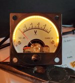
Well, I did get my meters in and to answer the silly question I posed originally, the mounting hole required is 45mm round. I guess that's why they call them SQ-45 🙂. On a side note, I attempted to illuminate one of these cheap meters and am still debating whether it was a success or not. I like it but wonder if the C.O.B filament I used was a bit too long. The following images are in normal room light and in darkness feeding it roughly 2.5 volts. If anyone is curious about the filaments, they are 80mm C.O.B. bought at AliExpress. 10 pieces for $8.00 Can. shipping included. COB Filaments . The SQ-45 volt meters are also from across the pond. 4 of them was about $22.00 Can. shipped SQ-45.
Attachments


Pretty nice looking. Can you share a little more about how you did your modification? I have some of the same meters. I think the length is about right. The next shorter ones might be a bit short.
Last edited:
Happy to 🙂 This is probably more than is needed but I would have appreciated seeing how easy it is to do.Can you share a little more about how you did your modification?
1. Attach some leads to the COB filament at a 90 degree angle to the connection points. Just for reference, the end with a tiny hole through it is '+'
2. Pop open the meter by removing the 2 small Phillips screws at either side of the meter
3. When the housing is removed, you'll be left with the internals with a cheap white plastic shroud that needs to be popped off. It's easy and a bit of pressure will do it.
I approximated where the filament would lie and filed 2 small grooves to make space for the filament connections to be pressed in close
4. If you look around where I drilled my 2 holes in the face plate, you will see there is space to pass a wire through all the way to the back . Mark where your holes will be drilled and pop the 2 holding screws out. Drill out the faceplate holes but make sure it's supported as these things are flimsy. At the same time make your exit holes in the back of the meter. There's tons of space back there to add a resistor to dim your filament. There is an existing resistor back there for the meter. If you look close at the faceplate you can tell they used the same meter for various renditions and hand painted decimals and the 1 V at the end of the scale. A wee bit of whiteout there too 🙂
5. Feed your filament leads down through the holes and bring them out the back. Twisting the leads gently between your fingers will move the filament so that it fits almost perfectly in place. I used medium viscosity cyanoacrylate with a small feeding tube to run a bead around the outside edge and the shroud (cowl?). Press the connection points in tight as well right around where the grooves were filed. Plastics and crazy glue hate each other at the best of times. Perhaps there is a better adhesive to use. Before you put it back together, use a soft paint brush or air or whatever to blow out the residual crud from drilling. I had mine back together and inevitably some crap was floating around inside still. Let it sit for a bit and put it back together. I sent the stupid adjustment screw flying a few times as it's just pressure fit. That's it...we're done. Now if someone can point me in the right direction as to where to hook these up in Pete Millet's Engineers Amp 🙂
Last edited:
They are really neat aren't they? Just wanted to impart a little wisdom if you're going to do this...let the C.A glue set up before putting the meter back together. I had one of mine fog the cheap plastic 'glass'. This dumb *ss was in too much of a hurry to get it back together.Just ordered some of those COE filaments.
- Home
- Design & Build
- Parts
- S0-45 Panel Meter