For short term solution if not having another maybe. Can handle that CC. But I recommend stronger transconductance M2 types for original performance. Like the 9530 or the 9630.Hi, Salas. Could I use IRF9610(M2) for NEG ver. ? CC=150mA
Hello Salas,
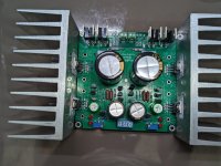
I am trying to build the ultrabib 1.3 but running into issues and wanted guidance.
I am attaching couple of photos of my build and wanted some clarifications. Target voltage is +15-0-15V for preamp. Transformer used is 15-0V dual secondary. R1 value of 2.2ohms for total current of 272mA, the preamp is supposed to take around 100mA.
On first fire up, the Rf burnt out with smoke and the LED's did not glow. I had kept it on for 2-3 seconds only cause I was not sure if everything was in order. To debug further, I need some inputs.
1. First mistake I did was to fire it up without cleaning the flux. This may have caused some shorts but the photos I have attached is after cleaning. I am not sure if this might have messed up the boards.
2. LED's used were Kingbright WP908A8ID. I am not sure this is ok to use but the specs seemed to match the older ones in BOM. The forward voltage is 2V and forward current is 20mA. On checking the latest BOM, I see that the current ones used are 10mA forward current. Please let me know if this could cause any issue.
Link for LED - https://www.digikey.in/en/products/detail/kingbright/WP908A8ID/2163742
3. C1 used is 10000uF and I am not sure if this is causing a large current to flow and causing the RF to burn up. Current value of Rf is 0.33ohms/1W. Should I increase the wattage of Rf?
4. I have used a large heatsink since I had it along with me. I am not sure if this will cause some oscillations but I have ensured the MOSFET tabs are insulated from the heatsink on all 4 transistors. The transistor legs are also long and I am not sure if this can cause any issue.
5. I checked the forward voltage of all small BJT and everyone of them seemed ok except Q1 on both positive and negative side which showed around 0.3V.
6. I checked the resistance between gate and drain of output mosfet and M2 on both positive and negative sides shows around 1-2Kohms and constant where as M1 keeps increasing (like it is charging the capacitor). The M2 may be gone but I am not sure. Should it show open circuit between gate and drain once they are soldered on the board?
7. JFET's used were J113 with currents of order of 20mA and hence I used the respective resistor values of 750ohms. I am not sure if JFET's survived and not sure how to test them.
Rest of the parts are as per the BOM. Please let me know your thoughts and thanks in advance.
Thanks
Attachments

First of all:
-Has the Mosfets insulation been checked for no continuity from metal tabs to sinks? Multimeter continuity buzzer mode is handy for that.
-Are all the active parts used coming from reliable well known vendors?
-Did you use this board design before? If it has any peculiarities I can't be of help, I don't know about them.
"Transformer used is 15-0V dual secondary"
So the transformer is two+two = four wire secondaries type I presume. When three wire center tapped it's incompatible because in Ubib there are two independent bridge rectifiers connecting to it.

Hello Salas,First of all:
-Has the Mosfets insulation been checked for no continuity from metal tabs to sinks? Multimeter continuity buzzer mode is handy for that.
-Are all the active parts used coming from reliable well known vendors?
-Did you use this board design before? If it has any peculiarities I can't be of help, I don't know about them.
"Transformer used is 15-0V dual secondary"
So the transformer is two+two = four wire secondaries type I presume. When three wire center tapped it's incompatible because in Ubib there are two independent bridge rectifiers connecting to it.
Thank you for your response. My answer in red.
-Has the Mosfets insulation been checked for no continuity from metal tabs to sinks? Multimeter continuity buzzer mode is handy for that. - Yes, I have checked and made sure the heatsinks are floating.
-Are all the active parts used coming from reliable well known vendors? - The M2 were procured locally and now that you mention this, I will change it to ones from reputed vendor.
-Did you use this board design before? If it has any peculiarities I can't be of help, I don't know about them. - I havent used this board earlier either but some of them have used and it seemed to work. I will build another one with genuine parts and let me see if it works.
"Transformer used is 15-0V dual secondary"
So the transformer is two+two = four wire secondaries type I presume. When three wire center tapped it's incompatible because in Ubib there are two
independent bridge rectifiers connecting to it. - Yes transformers are dual secondary and not center tapped.
Thanks
- Home
- Amplifiers
- Power Supplies
- Salas SSLV1.3 UltraBiB shunt regulator