Hello, after some time in research about Class-D modules to adapt on the Samson S700, I've finally decided to gets my hands dirty and I did an in-place amplifier topology change/mod for fun, I think it may be useful for users who have this heavy iron old Class-AB Pro amplifiers or similar.
As we know those old Samson S series(~1998) has the now obsolete/discontinued 2SJ78/2SK215 lateral MOSFET's, so I've opted to remove that section/parts and simplify its circuitry in favor simplicity and future proof of maintenance/servicing for years to come.
So I began carefully inspecting the newer(~2004) Samson series SX1200/1800 schematic and quickly found that they are essentially the same amplifier without the lateral MOSFET's circuitry complexity, so started tracing the PCB on the Samson S700 and found that I can simplify the amplifier on-place with a simple and clean modification, which also applies to all the Samson S series including the S500, S700, S1000, S1500 and S2000, though the S500 model has two amplifiers in a single module so may be a little more work but I will find out soon.
Lets begin with the modification, it simply consist of removing 14 parts, replacing one transistor(Q105) and making few jumpers and voila.
Prats removed:
1: D111, D112, D113, D114, D116, D118
2: R127, R128, R129, R130
3: Q106, Q107, Q109, Q110
Parts replaced(Optional):
1: Q105(2SC1567) replaced with 2SC4370 or equivalent(beware, Base/Emitter need pinout rewire).
Jumpers(assumes listed parts already removed):
1: On Q109/Q110, Pin-2 and Pin-3 tied together under PCB on each one.
2: On Q106/Q107(TO-92M) Pin-2 tied to Pin-1 of the Q109/Q110(TO-220) for each one above PCB, Note: Q106 to Q109 and Q107 to Q110.
Now after assembly, make sure to lower the BIAS pot to min before tests begins, will recommend the in-series bulb/resistor trick when setting BIAS before raw tests to minimize catastrophic damage.
Since an image can tell a thousand words, I will post few pictures of the early mod/test, though I still playing with and I will make a decent connection on the new BIAS transistor later on after re-order all the transistors for the finished product.
Some images of the early testing:
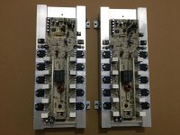
 The subject in the operating room.
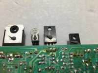
 Parts removed from one amplifier module.
 Under the PCB solder jumper in Q109.
 Under PCB solder jumper in Q110.
 Both jumpers shown on the MOSFET's location.
 Q106/Q109 top jumper example.
 Q107/Q110 top jumper example.
 Top view of the cleaner look on the amplifier module.
 Doing some testing on the Q105, always attached to the heatsink.
 Testing BIAS and playing some tones, offset voltage is almost zero like before about 1~2mv, however I've noticed the amplifier modules gets a bit more warmer without the lateral MOSFET's with around the same BIAS mv adjustment so caution on BIAS adjustment with the default pots.
Maybe some diehard Class-AB amplifier guru can explain what is the overal purpose of these laterals, there is no much info about it on the net nor found this topology on newer Pro amplifiers.🤔
Regards
Edit: Here are the schematics for the Samson S and SX series for reference:
 Samson S700/S1000 amp sch.
 Samson SX1200/SX1800 amp sch.
As we know those old Samson S series(~1998) has the now obsolete/discontinued 2SJ78/2SK215 lateral MOSFET's, so I've opted to remove that section/parts and simplify its circuitry in favor simplicity and future proof of maintenance/servicing for years to come.
So I began carefully inspecting the newer(~2004) Samson series SX1200/1800 schematic and quickly found that they are essentially the same amplifier without the lateral MOSFET's circuitry complexity, so started tracing the PCB on the Samson S700 and found that I can simplify the amplifier on-place with a simple and clean modification, which also applies to all the Samson S series including the S500, S700, S1000, S1500 and S2000, though the S500 model has two amplifiers in a single module so may be a little more work but I will find out soon.
Lets begin with the modification, it simply consist of removing 14 parts, replacing one transistor(Q105) and making few jumpers and voila.
Prats removed:
1: D111, D112, D113, D114, D116, D118
2: R127, R128, R129, R130
3: Q106, Q107, Q109, Q110
Parts replaced(Optional):
1: Q105(2SC1567) replaced with 2SC4370 or equivalent(beware, Base/Emitter need pinout rewire).
Jumpers(assumes listed parts already removed):
1: On Q109/Q110, Pin-2 and Pin-3 tied together under PCB on each one.
2: On Q106/Q107(TO-92M) Pin-2 tied to Pin-1 of the Q109/Q110(TO-220) for each one above PCB, Note: Q106 to Q109 and Q107 to Q110.
Now after assembly, make sure to lower the BIAS pot to min before tests begins, will recommend the in-series bulb/resistor trick when setting BIAS before raw tests to minimize catastrophic damage.
Since an image can tell a thousand words, I will post few pictures of the early mod/test, though I still playing with and I will make a decent connection on the new BIAS transistor later on after re-order all the transistors for the finished product.
Some images of the early testing:
The subject in the operating room.Parts removed from one amplifier module.Under the PCB solder jumper in Q109.Under PCB solder jumper in Q110.Both jumpers shown on the MOSFET's location.Q106/Q109 top jumper example.Q107/Q110 top jumper example.Top view of the cleaner look on the amplifier module.Doing some testing on the Q105, always attached to the heatsink.Testing BIAS and playing some tones, offset voltage is almost zero like before about 1~2mv, however I've noticed the amplifier modules gets a bit more warmer without the lateral MOSFET's with around the same BIAS mv adjustment so caution on BIAS adjustment with the default pots.Maybe some diehard Class-AB amplifier guru can explain what is the overal purpose of these laterals, there is no much info about it on the net nor found this topology on newer Pro amplifiers.🤔
Regards
Edit: Here are the schematics for the Samson S and SX series for reference:
Samson S700/S1000 amp sch. Samson SX1200/SX1800 amp sch.
Last edited:

Terribly realized and terribly sounding solder joints. I would desolder and re-solder them all. But: solder joints with minimal solder! One must be able to look through the solder holes of the board after soldering;-)
Simple and puristic follower that sounds very good by PP standards. I would also use as follower only: Simply place the input between R118 and R119. Just try;-)
Simple and puristic follower that sounds very good by PP standards. I would also use as follower only: Simply place the input between R118 and R119. Just try;-)
Hi cumb thanks for the input, I have to admit that the early posted S700 amp module mod is still a test bed example and still testing different BIAS transistor and the modified output section from original 3-pairs to 5-pair output transistors, I'm still seriously considering to re-design the boards with a two layer PCB's and order them from JLCPCB, however I can't ear any improvement/difference against my others stock Samson S series amplifiers subjectively though, also will try replacing the 5W 0.47 ohm resistor by non inductive ones but non sure if it will worth the money vs any noticeable difference by ear.Terribly realized and terribly sounding solder joints. I would desolder and re-solder them all. But: solder joints with minimal solder! One must be able to look through the solder holes of the board after soldering;-)
Simple and puristic follower that sounds very good by PP standards. I would also use as follower only: Simply place the input between R118 and R119. Just try;-)
As for placing the input between R118/R119, definitely sound very tempting and I thinking on test it as well, though dunno if this may effect the servo circuit, plus this amplifier has a separate buffer board for the balanced inputs and RF filtering, then single-ended to the amplifier modules like shown below:

Hope final mods worth the extra money/hassle and also considering testing lower noise socketed op-amps though it may be a rabbit hole, between I will definitely keep this old heavy-iron amplifiers since they are built like a tank and very hackable unlike the modern trend.
Regards
![DSCN0250[1].JPG](/community/data/attachments/1058/1058025-07f35674288bc3acf33ca551f02da858.jpg?hash=B_NWdCiLw6)
Yeah, two layers+ board may help reduce jumpering, biffier grounding and grouping ability, but at this point I'm considering getting a new scope to compare it againts the stock amp, lets see.Paralleling of parts to get ONE circuit! Something to scratch the head - nobody did and does(-:
Regards
Small update:
After playing around some more, I wanted to test the stock Panasonic 2SC1567A Q105 with the modded module, so I placed it in a small heatsink, powered the amplifier and set bias to about ~13.5mv and monitored temperature, I found that there is no heat issues at all so I can confirm that Q105(2SC1567A) works fine and can be left there.
Here is the final mod Samson S700 schematic for reference:

Regards
After playing around some more, I wanted to test the stock Panasonic 2SC1567A Q105 with the modded module, so I placed it in a small heatsink, powered the amplifier and set bias to about ~13.5mv and monitored temperature, I found that there is no heat issues at all so I can confirm that Q105(2SC1567A) works fine and can be left there.
Here is the final mod Samson S700 schematic for reference:
Regards
Update on this project.
After playing with this amplifier I've finally received the new complementary drivers from Profusion(more on that here) and made a few more changes on the circuit, I've upgraded the 10K BIAS pot with Bourns 3266W-1-103LF for a smoother adjustment, I've also replaced the base resistors R131/R132 from 47-ohms to 100-ohms for the new 2SA1837/2SC4793 like I've seen on few designs using this drivers.
So here was the final testing metod:
1: I've set the BIAS pots to minimum.
2: Connected and tested each module at once through a 150W bulb with BIAS at minimum.
3: Bypassed the 150W bulb with a 1A fast blow fuse after amplifier fully charged/turned on(to get maximum voltages).
4: I've set the BIAS to factory default of ~10mV until the amplifier get extensively tested for a while.
5: After BIAS stabilized re-adjusted to about 10mV, now ready for a listening test.
So during initial listening test I was pretty amazed by the punch and clarity of the amplifier at very loud volumes, definitely the amp sounds better without those laterals/extra part, though It may be the upgraded drivers as well, however this is purely subjective impressions as I haven't take any distortion measurements.
Here are some images of the final mod/repair of the Samson S700:

 Removed the excess of solder under the pcb and placed top jumpers on the Q109/Q110 instead.

 New UTC drivers and Bourns BIAS pot.
 R131 and R132 changed to 100-ohms fuse-resistor.
 All hooked-up and ready to smash the midbasses.
 Stock Amplifier before being modified to 10 output transistors per module for reference.
 Amplifier under test/auditioning with known tracks, the top Samson S500(high-pass amp) will also be modified and the laterals/extra parts will be also removed, it will feature the new UTC 2SA1837/2SC4793 drivers but the good stock Sanken output transistors 2SA1492/2SC3856 will remain there.
So the overall amplifier mod/repair was a lot of fun and a great learning experience with surprising results.
Regards
After playing with this amplifier I've finally received the new complementary drivers from Profusion(more on that here) and made a few more changes on the circuit, I've upgraded the 10K BIAS pot with Bourns 3266W-1-103LF for a smoother adjustment, I've also replaced the base resistors R131/R132 from 47-ohms to 100-ohms for the new 2SA1837/2SC4793 like I've seen on few designs using this drivers.
So here was the final testing metod:
1: I've set the BIAS pots to minimum.
2: Connected and tested each module at once through a 150W bulb with BIAS at minimum.
3: Bypassed the 150W bulb with a 1A fast blow fuse after amplifier fully charged/turned on(to get maximum voltages).
4: I've set the BIAS to factory default of ~10mV until the amplifier get extensively tested for a while.
5: After BIAS stabilized re-adjusted to about 10mV, now ready for a listening test.
So during initial listening test I was pretty amazed by the punch and clarity of the amplifier at very loud volumes, definitely the amp sounds better without those laterals/extra part, though It may be the upgraded drivers as well, however this is purely subjective impressions as I haven't take any distortion measurements.
Here are some images of the final mod/repair of the Samson S700:
Removed the excess of solder under the pcb and placed top jumpers on the Q109/Q110 instead. New UTC drivers and Bourns BIAS pot. R131 and R132 changed to 100-ohms fuse-resistor. All hooked-up and ready to smash the midbasses. Stock Amplifier before being modified to 10 output transistors per module for reference. Amplifier under test/auditioning with known tracks, the top Samson S500(high-pass amp) will also be modified and the laterals/extra parts will be also removed, it will feature the new UTC 2SA1837/2SC4793 drivers but the good stock Sanken output transistors 2SA1492/2SC3856 will remain there.So the overall amplifier mod/repair was a lot of fun and a great learning experience with surprising results.
Regards
Attachments


- Home
- Amplifiers
- Solid State
- Samson S series DIY lateral MOSFET removal, simplified amplifier circuitry