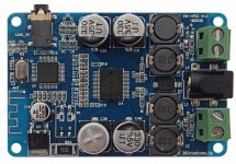
For fun i bought this tiny TDA7492P module from Sanwu.
TDA7492P Wireless Bluetooth 4.0 Audio Receiver Digital Amplifier Board 50W+50W | eBay
No fancy buttons, mic etc, just plain Bluetooth + Line-In.
The module is not "dead silent", there's some noise, but not from digital domain. Another nice feature is the signal amplitude driven automute-function.
While poking around on the board to get the pinout of the BT chip (sanded down) i thought, the 4 vias at the bottom are something like TTL UART. Well, no, it's USB and the module's enumerating as an USB audio device.
Now we have BT + Line-In + DAC (16bit/48kHz) + Amp for less than $7.50.
A shame that the BT-DAC is SE only.
(The Bluetooth chipset is from "ZhuHai JieLi Technology")
Last edited:

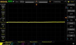
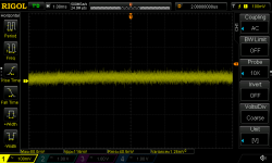
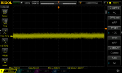
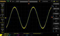
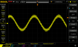
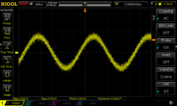
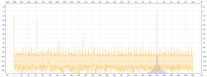
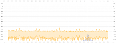
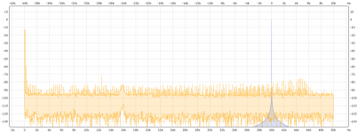
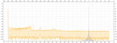
Some first insights for an unmodified board.
Measured between the BT chip DAC output and the TDA7492P input decoupling capacitor.
Muted (No signal input/stream):

Unmuted with BT input:

Unmuted with line input:

1kHz 100mVrms input signal via BT stream:

1kHz 100mVrms input signal via line in:

1kHz ~1Vrms input signal via BT stream:

1kHz ~1Vrms input signal via line in:

Measured between the BT chip DAC output and the TDA7492P input decoupling capacitor.
Muted (No signal input/stream):
Unmuted with BT input:
Unmuted with line input:
1kHz 100mVrms input signal via BT stream:
1kHz 100mVrms input signal via line in:
1kHz ~1Vrms input signal via BT stream:
1kHz ~1Vrms input signal via line in:
Attachments
-
 Muted_TDA7492P_input_cap_bt_input_signal.png27.1 KB · Views: 1,353
 -
 Unmuted_TDA7492P_input_cap_bt_input_signal.png43.9 KB · Views: 1,309
 -
 Unmuted_TDA7492P_input_cap_line_input_signal.png43.3 KB · Views: 1,290
 -
 1kHz_1Vrms_at_TDA7492P_input_cap_line_input_signal.png32.8 KB · Views: 1,264
 -
 1kHz_1Vrms_at_TDA7492P_input_cap_bt_input_signal.png33.4 KB · Views: 1,277
 -
 1kHz_100mVrms_at_TDA7492P_input_cap_line_input_signal.png41.5 KB · Views: 1,259
 -
 1kHz_100mVrms_at_TDA7492P_input_cap_bt_input_signal.png42 KB · Views: 1,304
Last edited:
Output signals into 4R resistive load at PVCC=24V
1kHz 4.12Vrms with BT stream:

1kHz 4.12Vrms with line in:

1kHz via line in before clipping:

1kHz via line in light clipping:

4.12Vrms -> 4.24Wrms
7.46Vrms -> 13.9Wrms
9.32Vrms -> 21.7Wrms
1kHz 4.12Vrms with BT stream:
1kHz 4.12Vrms with line in:
1kHz via line in before clipping:
1kHz via line in light clipping:
4.12Vrms -> 4.24Wrms
7.46Vrms -> 13.9Wrms
9.32Vrms -> 21.7Wrms
Attachments
-
 1kHz_light_clipping_at_TDA7492P_output_into_4R_bt_input_signal.png.png29.8 KB · Views: 1,194
 -
 1kHz_before_clipping_at_TDA7492P_output_into_4R_bt_input_signal.png.png28.6 KB · Views: 1,203
 -
 1kHz_4.12Vrms_at_TDA7492P_output_into_4R_line_input_signal.png.png28.7 KB · Views: 1,202
 -
 1kHz_4.12Vrms_at_TDA7492P_output_into_4R_bt_input_signal.png28.7 KB · Views: 1,200
The Bluetooth chip is a v2.1, a little long in the tooth! (pun)For fun i bought this tiny TDA7492P module from Sanwu.
TDA7492P Wireless Bluetooth 4.0 Audio Receiver Digital Amplifier Board 50W+50W | eBay
No fancy buttons, mic etc, just plain Bluetooth + Line-In.
The module is not "dead silent", there's some noise, but not from digital domain. Another nice feature is the signal amplitude driven automute-function.
While poking around on the board to get the pinout of the BT chip (sanded down) i thought, the 4 vias at the bottom are something like TTL UART. Well, no, it's USB and the module's enumerating as an USB audio device.
Now we have BT + Line-In + DAC (16bit/48kHz) + Amp for less than $7.50.
A shame that the BT-DAC is SE only.
(The Bluetooth chipset is from "ZhuHai JieLi Technology")
Difference between Bluetooth versions | v1.2 v2.0 v2.1 v3.0 v4.0 v4.1
The caps used (330uF 35V), are 2000h Non-Low-ESR.
From datasheet here:
Cheap capacitors from China / Taiwan / Asia - #360customs
they are specified for 247mA ripple current, x1.5 for frequencies >= 10kHz - so 371mA.
ESR measured (10kHz):
70mR @ 50°C
200mR @ 20°C
From datasheet here:
Cheap capacitors from China / Taiwan / Asia - #360customs
they are specified for 247mA ripple current, x1.5 for frequencies >= 10kHz - so 371mA.
ESR measured (10kHz):
70mR @ 50°C
200mR @ 20°C
To get the static noise a bit down, R01 + R02 (0R) needs to be removed to set the Gain to the minimum of 22dB.
With a source providing ~900mVrms signal, it's still possible to drive the amp into light clipping at 24V and 4R load at the lowest gain setting. This is even more true for lower supply voltages (like 12V).
Minimum Gain with 950mVrms equivalent via BT stream into 4R at 24V:

From the point of audio quality the BT chipset (AC4601) isn't as "crisp" as a CSR based chipset. The sound is a bit (subjective) "muddy" in the upper frequencies compared to MP3/AAC direct stream or even APT-X.
With a source providing ~900mVrms signal, it's still possible to drive the amp into light clipping at 24V and 4R load at the lowest gain setting. This is even more true for lower supply voltages (like 12V).
Minimum Gain with 950mVrms equivalent via BT stream into 4R at 24V:
From the point of audio quality the BT chipset (AC4601) isn't as "crisp" as a CSR based chipset. The sound is a bit (subjective) "muddy" in the upper frequencies compared to MP3/AAC direct stream or even APT-X.
Attachments
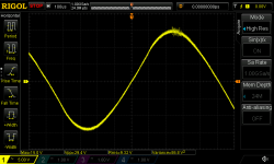
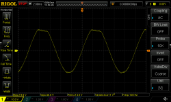
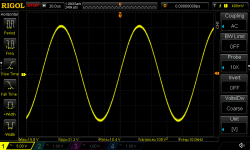
Anyone noticed the slightly distortet sinewave at high output level? Well, let's see.
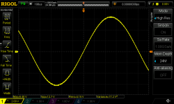
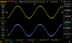
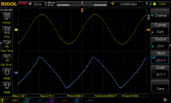
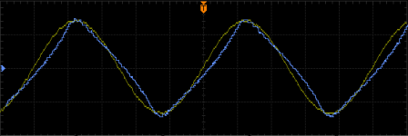
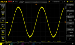
First compare 4R (blue) vs. 8R (yellow) load at 1kHz:

overlayed:

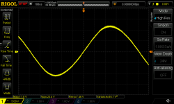
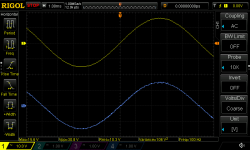
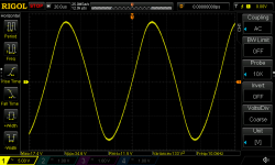
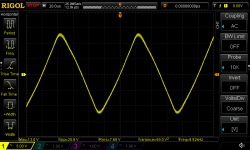
Now at 100Hz:

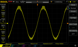
Bit better. So whats going on on the other side - i.e. 10kHz:

No matter if 4R or 8R load, the sinewave is distorted.
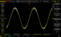
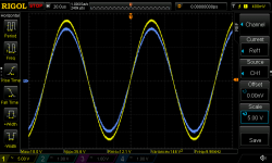
Comparing the input signal (right at the input coupling capacitor at the TDA7492P) with the output signal at 4R:

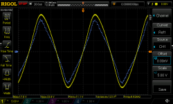
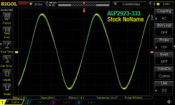
Maybe an inductor saturation problem? Let's change for a AGP2933-333KL inductor which should be more than adequate:
AGP2933-333KL 10kHz into 8R:

Compared to the stock inductors:

Pretty much equal.
First compare 4R (blue) vs. 8R (yellow) load at 1kHz:
overlayed:
Now at 100Hz:
Bit better. So whats going on on the other side - i.e. 10kHz:
No matter if 4R or 8R load, the sinewave is distorted.
Comparing the input signal (right at the input coupling capacitor at the TDA7492P) with the output signal at 4R:
Maybe an inductor saturation problem? Let's change for a AGP2933-333KL inductor which should be more than adequate:
AGP2933-333KL 10kHz into 8R:
Compared to the stock inductors:
Pretty much equal.
Attachments
-
 8R_4R_comparison_1khz_unclipped.png32.5 KB · Views: 1,183
 -
 8R_4R_comparison_1khz_unclipped_2.png35.5 KB · Views: 1,166
 -
 8R_4R_comparison_100hz_unclipped.png27.2 KB · Views: 1,162
 -
 8R_4R_comparison_10khz_unclipped.png36.4 KB · Views: 1,165
 -
 8R_10k_Distortion.png20.9 KB · Views: 1,136
 -
 8R_10kHz_AGP2923.png33.4 KB · Views: 1,147
 -
 10kHz_sine_into_4R_comparison.png29.5 KB · Views: 1,158
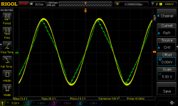
Maybe the output filter capacitor? Tried an 470nF MKP:

Same story.. so the distortion comes from the TDA7492P itself. More distortion st higher frequency. (The datasheet already gave a hint)
How about clipping symmetry?
100Hz into 8R into Clipping:

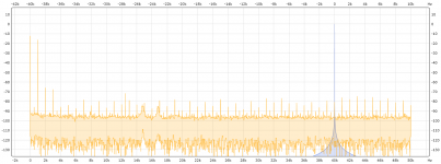
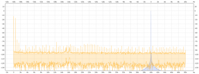
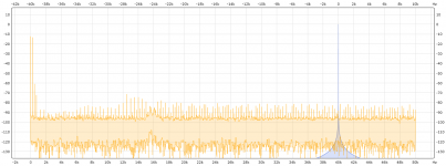
At last some FFT into 4R for different frequencies all done at 4.2Vrms output level:
31.5Hz:

125Hz:

250Hz:

500Hz:

1kHz:

6.4kHz:

10kHz:

Same story.. so the distortion comes from the TDA7492P itself. More distortion st higher frequency. (The datasheet already gave a hint)
How about clipping symmetry?
100Hz into 8R into Clipping:
At last some FFT into 4R for different frequencies all done at 4.2Vrms output level:
31.5Hz:
125Hz:
250Hz:
500Hz:
1kHz:
6.4kHz:
10kHz:
Attachments
-
 4R_10kHz_Stock_Inductor_MKP.png32.8 KB · Views: 772
 -
 8R_100Hz_unsymm_Clipping.png27.6 KB · Views: 782
 -
 1kHz_4.2Vrms_into_4R.png65.2 KB · Views: 772
 -
 500Hz_4.2Vrms_into_4R.png64.8 KB · Views: 767
 -
 250Hz_4.2Vrms_into_4R.png64.8 KB · Views: 818
 -
 6k4Hz_4.2Vrms_into_4R.png65.5 KB · Views: 766
 -
 10kHz_4.2Vrms_into_4R.png63.5 KB · Views: 793
 -
 125Hz_4.2Vrms_into_4R.png64.4 KB · Views: 773
 -
 31H5z_4.2Vrms_into_4R.png64.3 KB · Views: 796
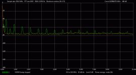
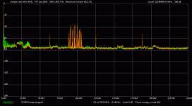
Muted inputs into 4R, checking "radiation" or leftover from switching frequency after the output filter:


Orange is reference, when amplifier is off.

Orange is reference, when amplifier is off.
Attachments
Last edited:
Last thing to do was the modification of the output filter.
Stock where: 2x33uH + 470n + 2x100n (AD-Filter)
modified is: 10uH + 2x1u FKP (BD filter)
With only changing the inductors to 10uH and the AD filter capacitor from 470n to 1u it went like this:
4R 10kHz before clipping:

Changing the AD-filter to BD-filter gives:
4R 10kHz before clipping:

Both 4R and 8R looking fine now:

Comparing this filter against the other channels original filter:
4R 10kHz before clipping (green unmodified, yellow modified):

Inductors used: Coilcraft MSS1278-103MLB
Capacitors: TDK 1u 63V FKP
Stock where: 2x33uH + 470n + 2x100n (AD-Filter)
modified is: 10uH + 2x1u FKP (BD filter)
With only changing the inductors to 10uH and the AD filter capacitor from 470n to 1u it went like this:
4R 10kHz before clipping:
Changing the AD-filter to BD-filter gives:
4R 10kHz before clipping:
Both 4R and 8R looking fine now:
Comparing this filter against the other channels original filter:
4R 10kHz before clipping (green unmodified, yellow modified):
Inductors used: Coilcraft MSS1278-103MLB
Capacitors: TDK 1u 63V FKP
Attachments
Yes, i did, no "visible" change. Distortion is mainly generated from inductor saturation and filter configuration.
Even with the fixed output filter, the BT chip / link quality is dominating the sound, which is SBC at best.
@indoubt,
if you can see signal deformation already on the scope, you'll here hear it for sure. Distortion levels under 1% are hard/not to see.
I wouldn't recommend this board, even with modifications, the BT module is limiting the performance. The CSR based boards are a better choice, especially as they can be reprogrammed.
Last edited:
- Home
- Amplifiers
- Class D
- Sanwu TDA7492P + Bluetooth 2.1